66 dart LED prototype working for now

Looks like you are doing thoughtful, skillful good work on this. Please be aware that the exterior lights have to work properly in all respects -- eyeballing it, even with an expert eye, and assessing it "Yep, looks good!" isn't enough to guarantee adequate safety performance from homemade vehicle lights. It sounds like you're building these for your own car and not for production and commercial sale; I'm not suggesting you have to go to the trouble and expense of sending your lamps for compliance testing (though liability with uncertified safety lights is an issue worth keeping in mind), but you should at least be aware of the factors that go into whether a brake light, tail light, parking light, turn signal or other safety light works adequately.

•Rear intensity in dim tail mode (2cd minimum on axis, 18cd maximum anywhere in the beam)

• Rear intensity in bright brake mode (80cd minimum on axis, 300cd maximum anywhere)
• Front intensity in dim park mode (4cd minimum on axis, 125cd maximum anywhere)
• Front intensity in bright turn mode (200cd minimum on axis, no maximum)
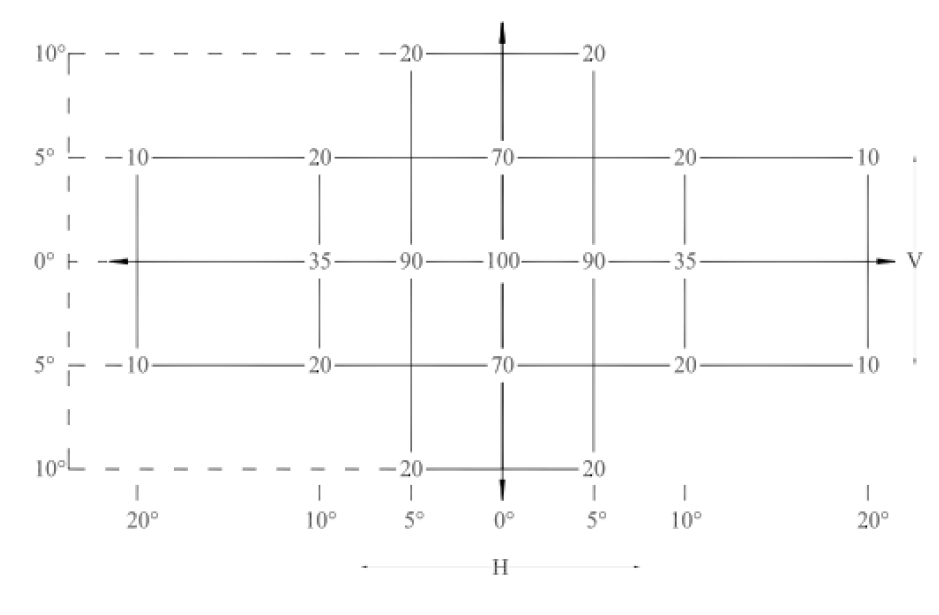
•Intensity throughout the required spread range of vertical and horizontal angles; multiply the minimum requirement by the percentage values in this table to get the requirements for the various test angles:


You can see the center of the grid is "100", that represents 100% of the axial minimum intensity values listed above. At 5° left and 5°right on the horizontal, you need 90% of the minimum axial intensity value. At 10°left and 10° right on the horizontal, you need 35% of the axial minimum, and so on. These requirements are so that the lights convey their message accurately and unambiguously to drivers located anywhere within relevant seeing range...up high in a semi tractor, down low in a Corvette, one or two lanes over or approaching on an on-ramp, etc.

• Intensity ratio, bright:dim. The brake (or front turn) lamp must give at least three times the intensity of the tail (or front parking) light, except on axis as well as 5°left and right on the horizontal and 5° up on the vertical, at which points the brake (or front turn) lamp must give at least five times the intensity of the tail (or front parking) lamp. This is important so that other drivers can immediately discern whether they're seeing a brake light or a tail light, or a turn signal or a parking lamp, without having to spend seconds watching the state change (bright to dim or dim to bright).

•Intensity maintenance at high and low ambient temperatures and with prolonged use. This is a toughie; LEDs' light output increases with decreasing temperature, and decreases with increasing temperature. You need to design your driver circuitry such that the lamps will produce light within the correct intensity ranges no matter how cold or hot it is outside, and the brake lights will remain above the minimum requirement even in traffic with extended usage. Either you need to seriously underdrive the emitters or you need very good heat sinking.

Please keep us up to date on how this project evolves![/quote

>>>>>>_________________________________________
nope just for my car(s) I hate the single outboard light that acts as a turn/brake/tail and the inboard one just a bright tail light

I was afraid of that.(my looks good wasn't going to work )

I did take a (don't know the name of the thing) photographer's light sensor/meter and check the readings @ 1 foot increments past 10 ft in varying degrees of up/down and left/right combo's (I wish I knew what the sensor was reading I'll see if I can borrow that thing again and google it)

stock was directly behind the car in a horizontal line with a cleaned and repainted housing (standard aliminium paint to match the original as close as possible and all lenses washed and polished
(when I went about 10 degrees down or up it didn't make much difference approximately 1-2 drop up to 25 degree's off horizontal) for the led's
90 degrees being directly behind going to either side until the light was blocked by the bezel. after 25 degrees going vertical it dropped 5-7 on the reading each 5 degrees again for the led's

degree ft intensity tail/brake
90 @ 10 1100 1645
80 10 1100 1645
70 10 1096 1644
65 10 1096 1643
60 10 1095 1643
55 10 1095 1643
50 10 1094 1643
45 10 1092 1642
40 10 1092 1642
35 10 1090 1642
30 10 0 hit the chrome bezel
25 hit the bezel on the other side
going the other way was with in 1-2 of the light sensor reading

led's were
degree ft intensity
90 @ 10 1628 2121
80 10 1628 2121
70 10 1627 2121
65 10 1627 2121
60 10 1627 2121
55 10 1627 2120
50 10 1625 2120
45 10 1625 2119
40 10 1625 2119
35 10 1624 2119
30 10 0 hit the chrome bezel
going the other way was with in 1 of the light sensor reading not much drop horizontal and verticle was in 5 degree increments similar to horizontal until 25-30 degree mark. then I lost about 5-7 each 5 degrees untill it was blocked by the bezel
>>>>>>>>>>>>+_____________________________________

I can tell you now that the front's won't make any of those untill I get the new Led's. then the front's are/should be close.

the back's are/should be close. (yeah I know the looks good enough syndrome) but it's all I have at this moment. I have a second car that I was using as a base for the lights and a friend has a caddy that I went against for the led's. mine are (look) more intense(again looks good syndrome). I want to cast some lenses that match his (reluctor?)inside of his lense has shapes that re-direct the leds differently than mine do.
really crisp light pattern,mine's not as crisp with pillow or pyramid style shape(you can see individual LED's through the lense but blurred instead of a row of leds like the caddy with circles over each led to diffuse it into the other led.
I'd settle for a better diffusion that what's stock.

as for heat sinking I have a row of 1/8 inch copper tubing flattened and shaped on the PCB
and large solder pads and I've got a friend that has a mill and he'll make custom heatsinks that fit my grounding strips for me cheap after I finalize a design.
and when I do have the pcb's made for me I'm having the copper pads and traces made as large as I can to help heat sink the led's
I have run the light on a 12 volt regulated power supply for over 24 hours each in both modes (brake and tail)using a digital thermometer saw a rise in temp of only 5 degrees in the housing on 95 degree days during those 24 hour runs. the last test I forgot to unhook the charger and left them running in brake mode friday night and all weekend until I got back out there on tuesday evening, the housing was 10 degrees hotter that the first test. I am going to use 12volt regulators for all led wiring to limit voltage spikes.
the only oops I made was trying to check the leds with power on and shorted a couple(bunch) of leds when a wire got loose and racked across the back side of the PCB took out a row and some singles. I'm replacing the led pcb with a complete new design that uses a better led from phillips
single chip 70 MA red/orange for the rear and yellow amber 70 MA for the fronts. it'll take a little different grouping but the shape and size stays the same.
thanks for your input on my led's. I'm excited about them and I hope they work out.