1985 D150 "Mr. Curtis" race truck with a 2015 6.4

-
It might fit, it might fit, it might fit!
Gotta check my measurements and put that 1500s control arm on stilts so it's close to the crossmember but i think we are on to something here!

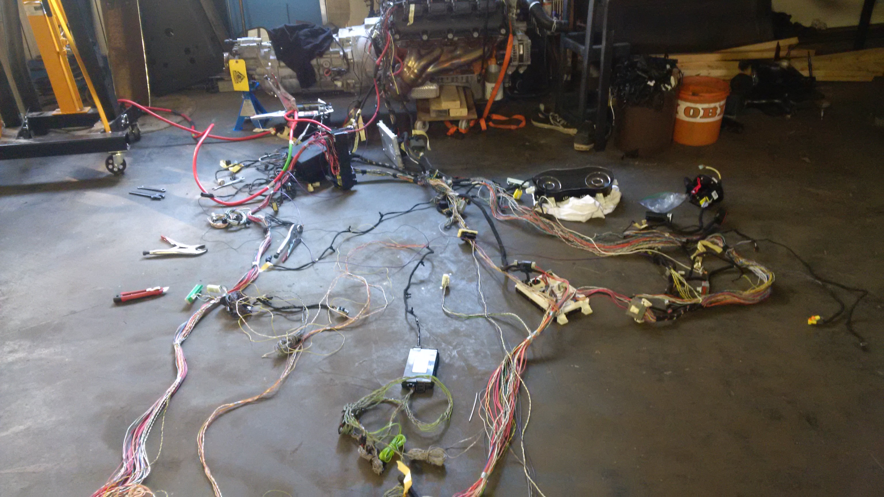
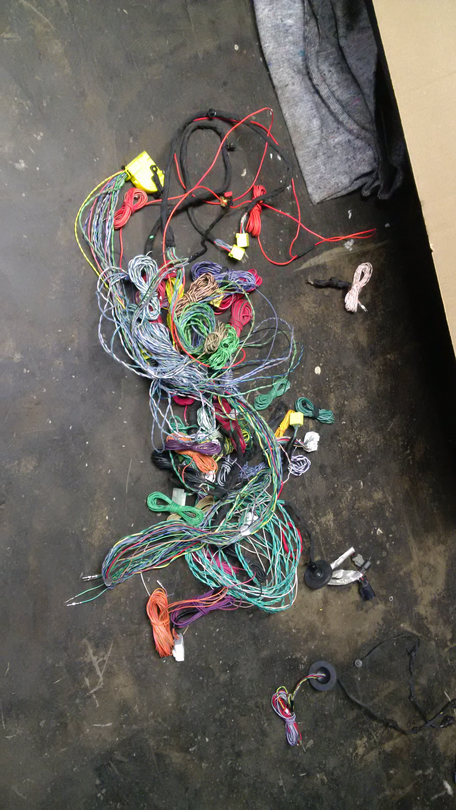
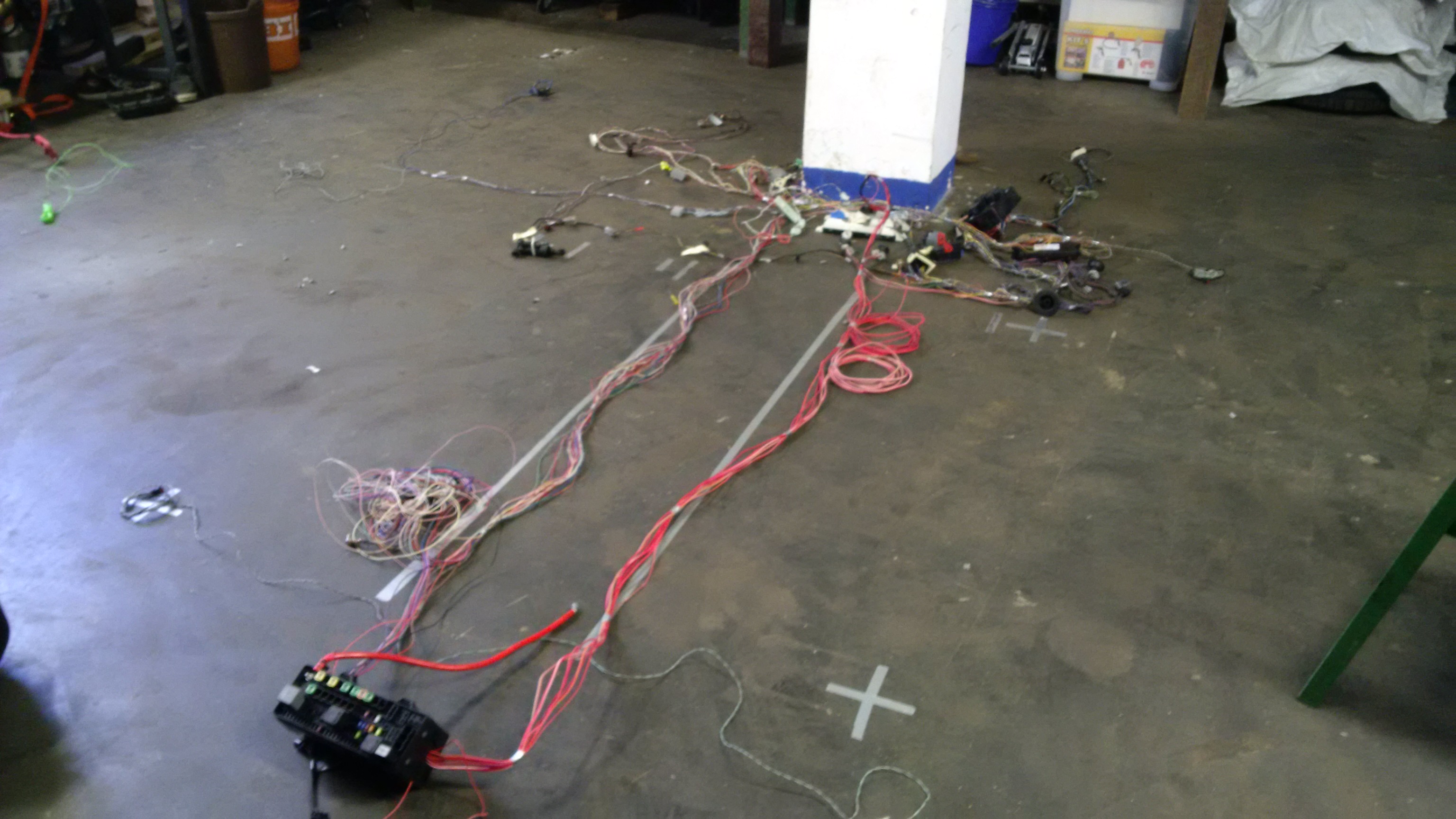
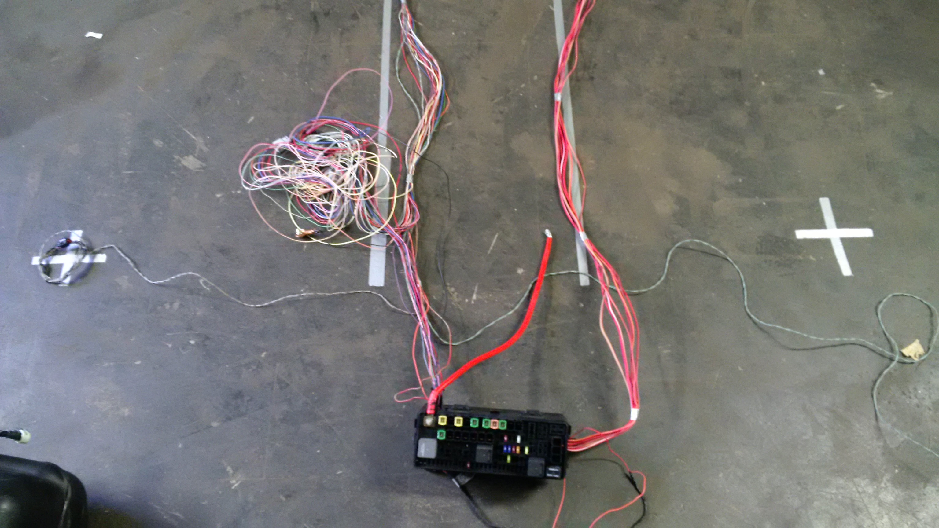
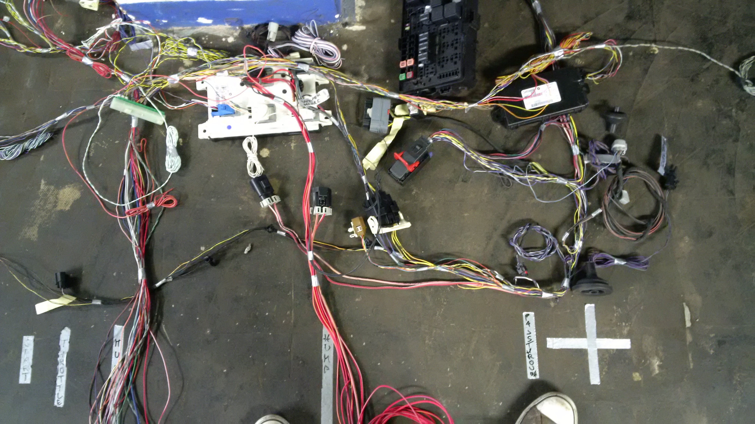
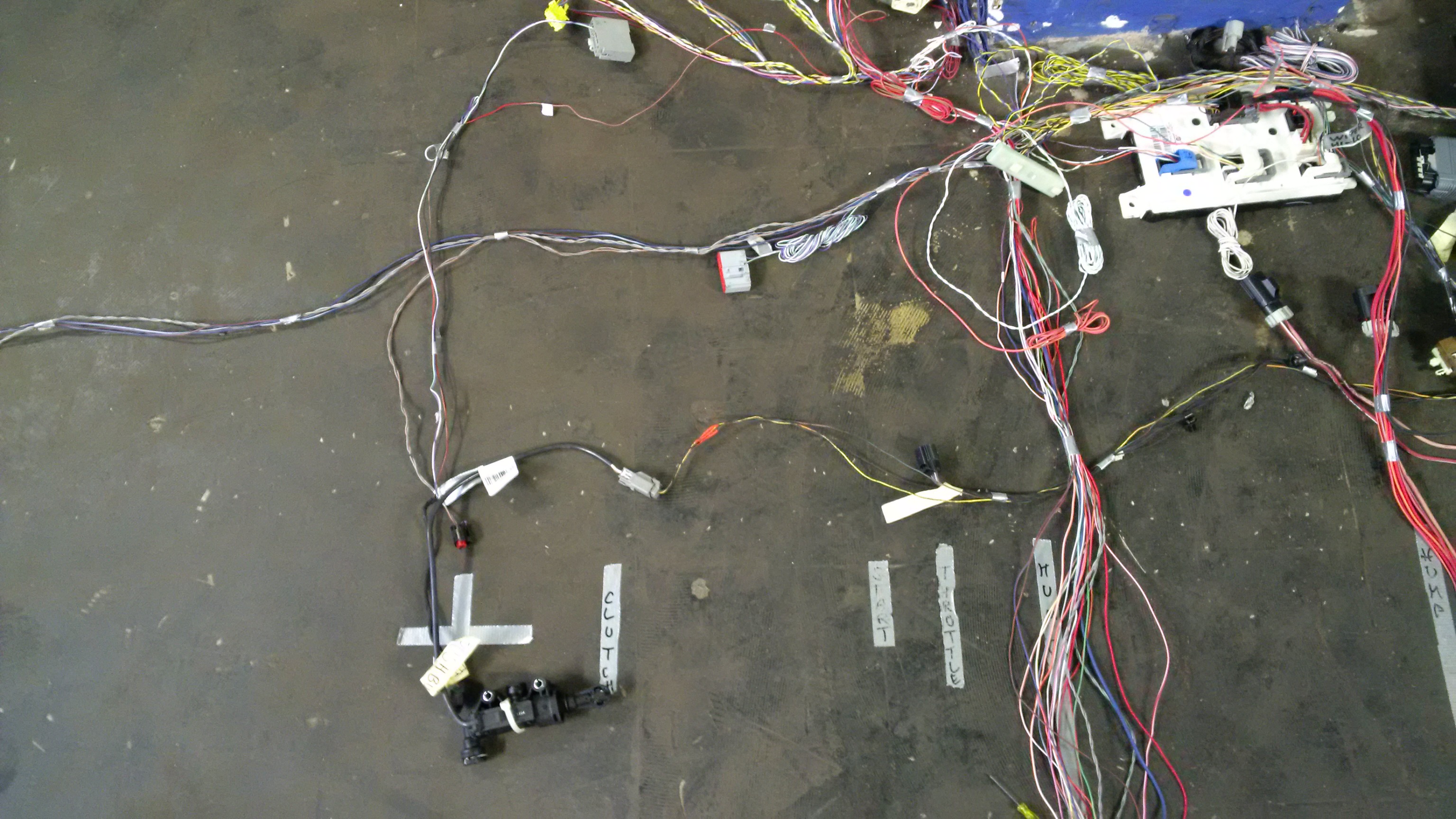
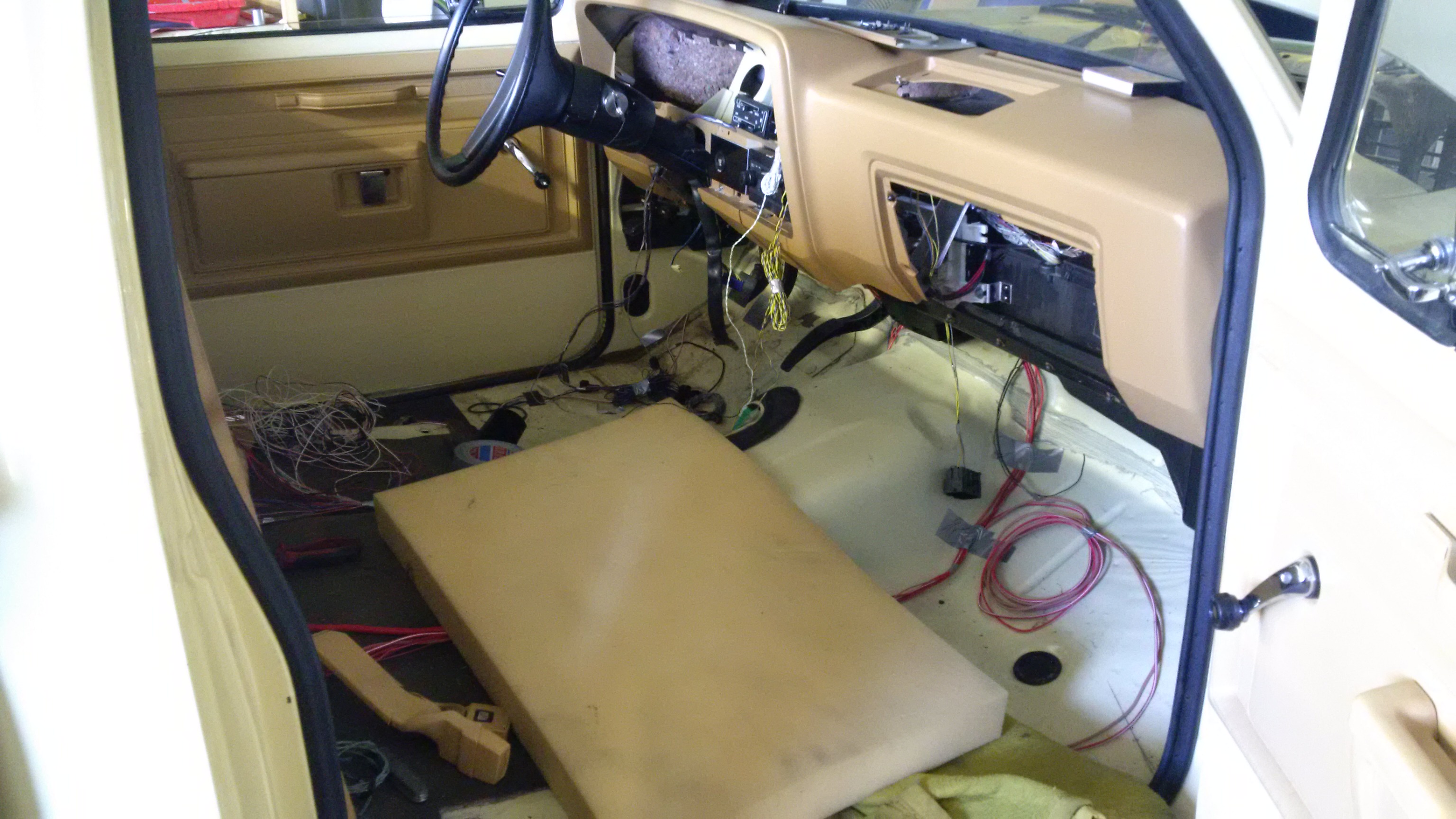
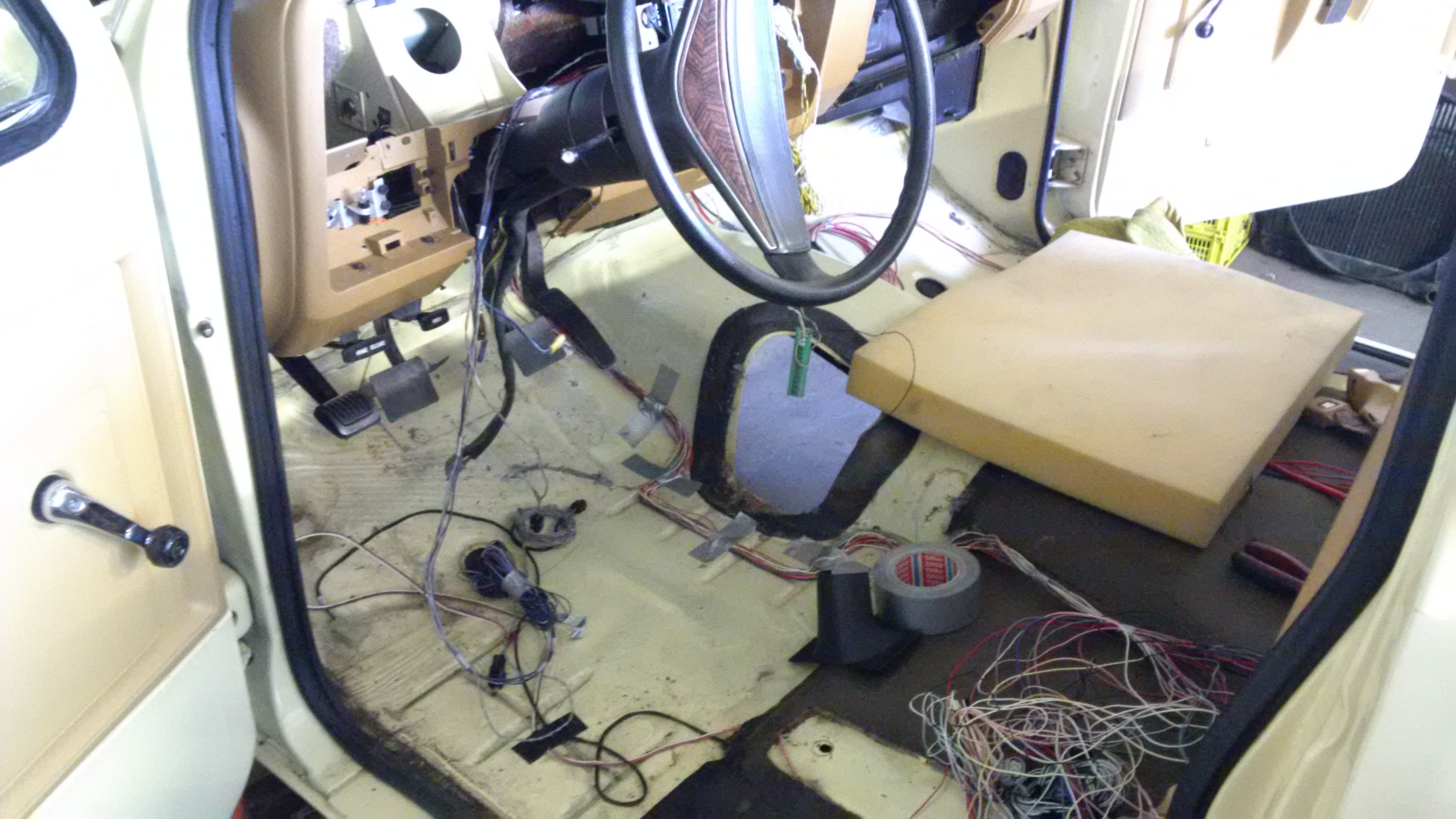
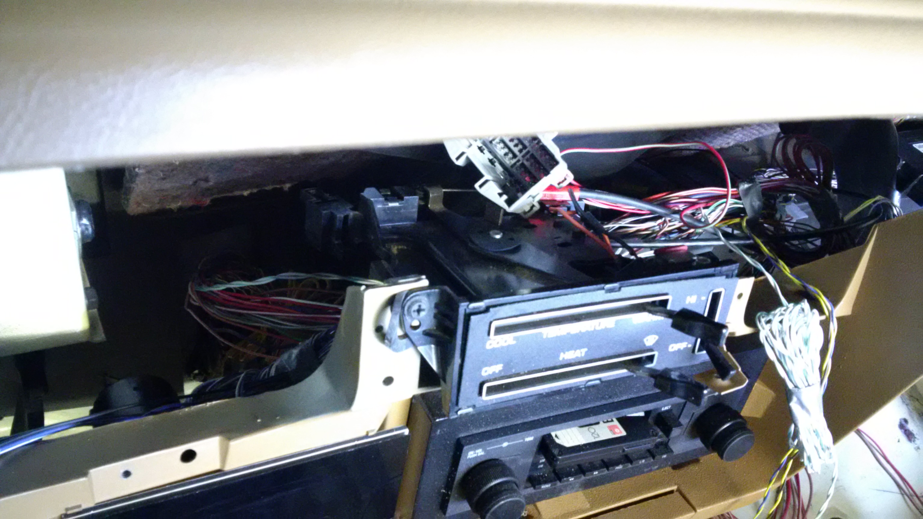
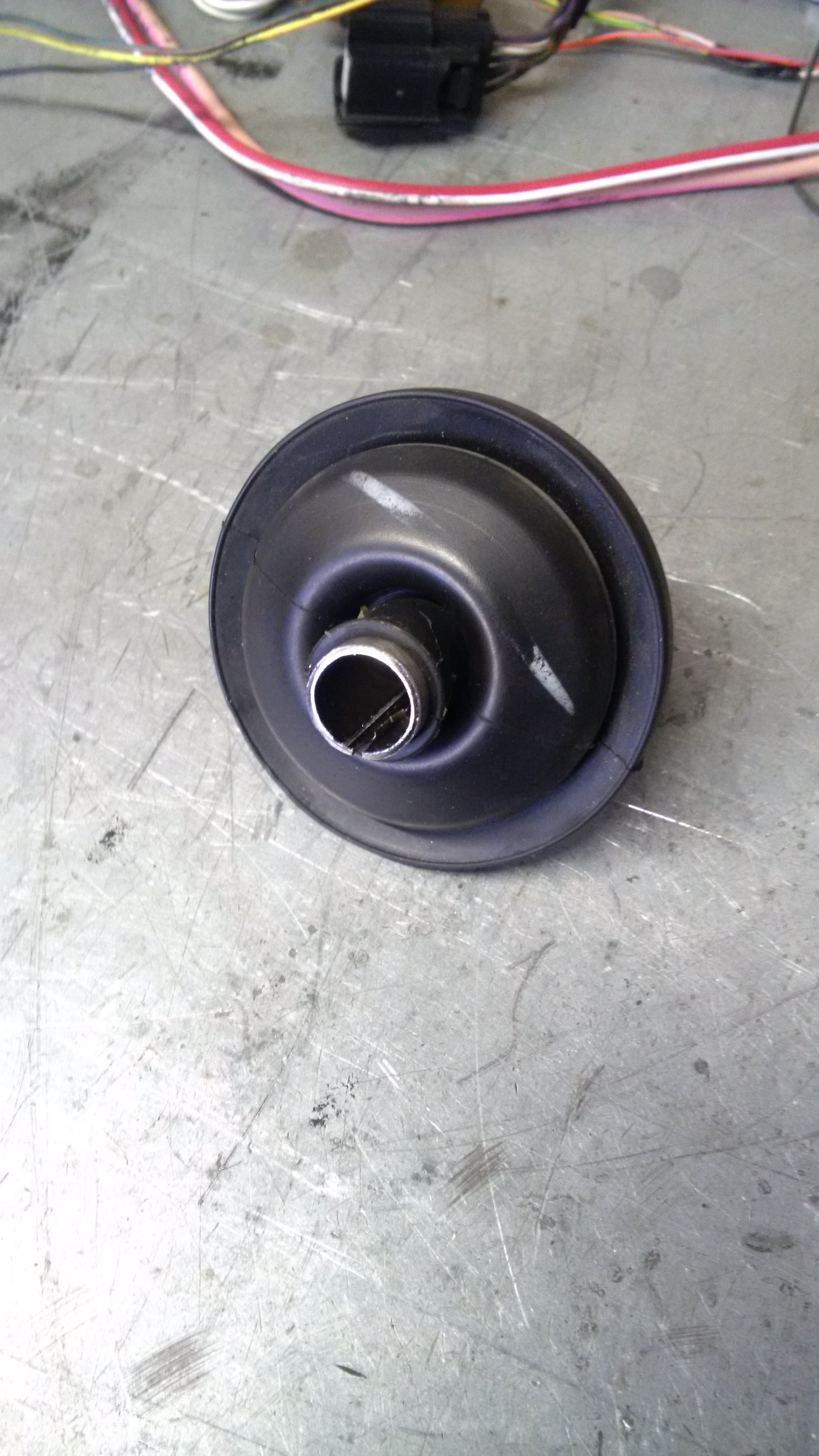
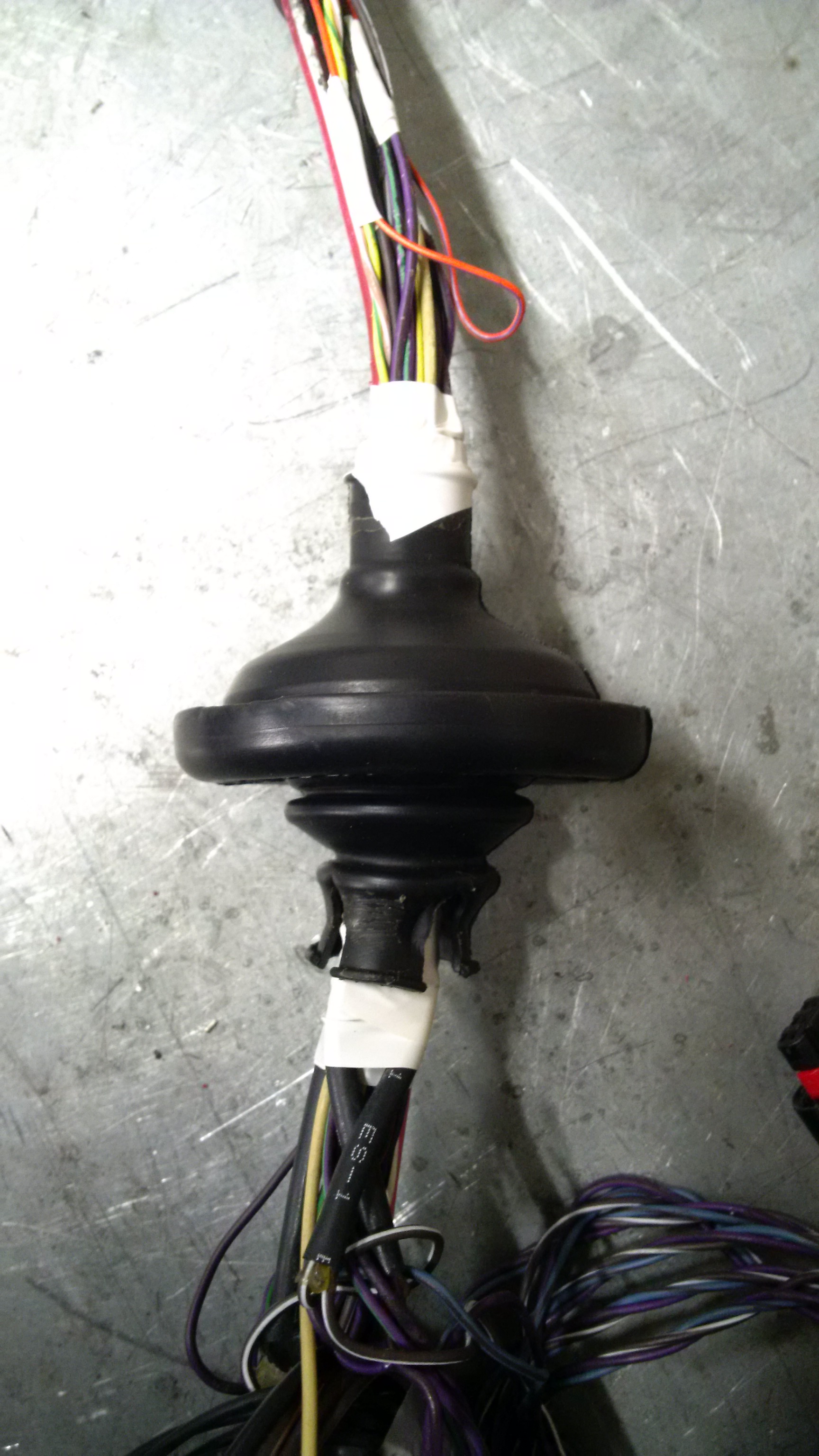
The rest of the day was spent by unwrapping the Challengers dash harness and beginning to understand its layout.
Slooooow process. 3 hours of unwrapping and understanding.

I need to get that FSM.
 
Last edited:
Even though I think I'm clever, I find laying it out on the floor with black marker and tape helps. This way my head doesn't get full of the measurements and I can look and visualize.

Putting the upper, lower and spindle together with smaller diameter bolts and clamps or tack welds and no spring can move it through travel and again try and visualize the package. It may seem crude but it has worked for me. Once I think it's close put it together with proper bolts and try again.
 
A milestone has been reached.


I started tearing into the wiring harnesses last week and got most of the unwanted stuff removed.
My milestone was, to thin out the harnesses and still have a running engine. As far as i can read, getting it to crank over is important:


The dash works as well. It complains about all the stuff that is not present anymore... i hope i can remove all of these from the configuration of the BCM.

img_20160903_161601.jpg


Test scenario:

img_20160903_161332.jpg


Quite a bunch of wiring removed, more to go. The dash harness is untouched, the engine compartment harness aswell.
No need to modify the engine harness other than relocating it a bit and maybe i will have to make new power cables because these might not fit as good.

img_20160903_191745.jpg
 
Today i got too goddamn greedy. My GF always wants me to be quicker at making decisions but when i am quick, i **** things up.


First things first.

img_20160905_140404.jpg


Mounting the throttle pedal was so easy it must have been one ingredient for the greedyness...

Bolts to the lower left of the two original holes of the original throttle pedal, drilled a new one, bolted up, almost done.
The pedal is located conveniently but it was too light for my liking.

Even easier fix with parts that are even meant to do exactly that:

img_20160905_140808.jpg


Old throttle return spring.

For a bit of adjustment i drilled a few more holes:

img_20160905_141430.jpg


And to top it off - you see i got really bored - i added some heat shrink tubing on the spring ends to stop noise:

img_20160905_141823.jpg


Yeah.
And then i decided i would continue beeing great and merge the two dash clusters.

Now i don't have a pristine D150 cluster any more and the cluster of the Challenger is destroyed as well.
(The housing, no the electronics.)

I won't show pics of that massacre. Let's just draw the blanket of silence over the topic and let me fill out a check for an IQ3 dash...


And now my effing pasta is oversalted. AAAAARGH!
 
Today was a good day. No effing around with the dash, just purely productive work.

First i picked up my passenger side SRT-10 spindle.
It came with the wheel bearing and i was able to confirm the measurements i took from a picture using a picture editing program.
Now all i have to do is align the spring properly... another "problem".


I continued with the wiring because i was "in the flow".

I hed the (to me) great idea to outline the cab on the shop floor with duct tape. So much easier to get a grasp of where everything goes.
Look for yourself, i got it pretty much layed out and ready for making all the ground connections and shortening/lengthening of wires.

img_20160907_183940.jpg


The inside fuse box goes to the back of the cab.

img_20160907_183948.jpg


Outside fusebox on the passenger fender, next to the ECU (not shown in pic).

img_20160907_183958.jpg


The BCM will be mounted on a bracket riveted to the heater box. I started to like riveting stuff. So much less trouble in fastening stuff to other stuff, lol.
As you can see, i layed out pretty much everything i had, including the pedals (clutch and throttle) and the antenna-box (the "controller" for the key-fob-antennas).
This one will be installed (double sided tape?) on the heater box.

img_20160907_184005.jpg


The next step is to throw the original wiring harness on top of that and graft them together...
I would really need the wiring diagrams for that though and Techauthority did not ship my order yet.

I really wanted to separate the high current power cables from the signal cables, just in case one fries...
 
Ha, best idea ever to do the above. Because look what was super easy to do yesterday:

img_20160908_171314.jpg


img_20160908_171334.jpg


img_20160908_171343.jpg


I made a bracket for the BCM and riveted that bracket directly to the heater box. Mean but it works for now:

img_20160908_154227.jpg


img_20160908_160451.jpg


Then came the "pita but not hard"-part.
The engine room harness has to pass through a 2" hole in the cab.
It's 2" because i am re-using one of the OEM bushings and it was a pain because i had to make a metal sleeve so i could pass all the wiring through that bushing, which is essentially a bit too small for what i was asking it to do...

Remember to split the sleeve so you can remove it later:

img_20160908_181001.jpg


Then use a bit of silicone spray...

img_20160908_181018.jpg


... and needle nose pliers to do this:

img_20160908_181218.jpg


img_20160908_181441.jpg


Aaaand after doing it twice, because i had the bushing on the harness the wrong way and realized it after finishing the last connection, ta daaaa:

img_20160908_202152.jpg


Now i can shoot that 2" hole in the cab and continue...
 
I figured out how to drive the headlights over the BCM with the stock headlight switch.
All i need is a rewire of the headlight connector and three resistors.
The Challengers headlight switch is basically a switched resistor array, providing fixed resistances on each switch position. I am duplicating that. Easy as pie.
Well not exactly easy as cake but easy as "calculating the proper values for each resistor and figuring out where they have to go".

So that's down. If you had the option of installing a light/rain sensor, to have automatic wipers and headlights, would you do that?

It's not overly complicated, provided i find a flat spot on the windshield to mount the sensor to. Route three wires to that spot, connect and be done.
 
So that's down. If you had the option of installing a light/rain sensor, to have automatic wipers and headlights, would you do that?

It's not overly complicated, provided i find a flat spot on the windshield to mount the sensor to. Route three wires to that spot, connect and be done.
I would. It sounds like you have everything needed to do it so why not.
 
Getting anything to work with the 2015 technology is a great thing. Sometimes i am just happy when something small just works out as planned.
Which does not apply to any of the major exterior lighting features except the front turn signals. The tail lights (stop/turn are one LED lamp, driven by a pwm led driver) not so much.

Headlights and tail lights absolutely demand a proper signal coming back to the BCM over the fault sense wiring. Great.

Well, one is down, several more to go:


I had to rebuild the wiper linkage... all bushings gone, replaced with washers and cotter pins...


The resistors for the headlight switch showed up.
I also ordered a pair of tail light lamps (LED modules, in fact) to destroy them.
I need to find out how they actually work to be able to make a module that can drive incandescent bulbs instead of LEDs.

And i ordered a used wiper motor to figure out how to drive the stock wiper motor... only to find that i had the sense wire in the wrong position of the connector on the BCM.
Yay...


And these are pretty much self explaining:

scat-pack-emblems.jpg


The really hard stuff will be faking messages from the ABS module to make the BCM think there IS a working ABS module that sends messages.
Like "light the stop lamps".

Arduino to the rescue.
 
From now on i got's da control over da light and ole electrical darkness.

A couple of resistors, a few hours of fiddling and the ole light switch has been fitted with multiplex switching capabilities.

 
I will let you know when i take delivery.

I just ordered 690ft. of wire to continue building the body wiring harness, different colors and gauges of course.
 
Cut six feet of superflous length from the cab wiring harness today, re-established the connections, finished some loose ends and i am looking forward to build the frame harness this weekend.

I am also doing some research about using late model Ram door latches as a replacement for the manual door latches on my truck.
The wiring diagrams indicate they have similar wiring compared to the Challengers door latches and they have the 3-bolt bolt pattern.
Unfortunately this pattern has been turned around so the single bolt is below the striker, compared to the '85 trucks doors...

It's all just sheet metal here, so i am not too scared about making it fit. I am not going through all the hassle without having power door locks in the end.
 
Props to you for getting everything working with the factory harness and electronics, that stuff gives me nightmares.
 
I can't wait to see how you are able to get around not using the ABS module. It may be easier with the 6 speed ECM you have than with the auto trans. There will be less inputs needed.
 
ABS Module:
This gives ME nightmares.

There's either some kind of "easy" way around it to be able to make the BCM light up the stop lights (that i don't know of) or the really complicated way of making an Arduino with a Canbus shield fake an ABS module.
I would actually prefer the Arduino-way because that same Arduino could act as a display driver to mimic mechanical gauges.


@Buschi:
Bad VR, bad wiring (corrosion), faulty grounds. I buy most of the wiring parts i need at www.kabelknecht.de.
Drop me a line if you need help. It'll be a while until i am in the North again.
 
see my thread in HEMI swaps. brand new. have 15.5 Volts. new VR. suspecting the VR can't handle a modern alternator and require a Kind of HP VR... ? not sure on this.. pls have a short look...
 
ABS Module:
This gives ME nightmares.

There's either some kind of "easy" way around it to be able to make the BCM light up the stop lights (that i don't know of) or the really complicated way of making an Arduino with a Canbus shield fake an ABS module.
I would actually prefer the Arduino-way because that same Arduino could act as a display driver to mimic mechanical gauges.


@Buschi:
Bad VR, bad wiring (corrosion), faulty grounds. I buy most of the wiring parts i need at www.kabelknecht.de.
Drop me a line if you need help. It'll be a while until i am in the North again.

Have you thought about using the ABS module but not installing it to the hydraulic brake system. Just use it to communicate through.
This would allow you to use the brake position sensor and have the ABS module send a signal to the BCM to turn on the brake lights. With that though, you would need all of the inputs the ABS wants to see, wheel speed sensors, steering angle sensor, yaw rate sensor, etc. If you don't use ABS module and you do something different with the brake lights, will the ECM still stay out of 'limp home mode' without those inputs.
Have you looked into reprogramming the ECM? I'm not sure if its possible, but if you could just get the ECM to no look for the ABS inputs, that might be the easiest route.
These are all things I've been trying to figure out while planning my build too.
Good luck, keep us posted.
 
Funny thing, you're from Nampa, ID.
My '85 W250 has spent most of its life there :D Maybe you recognize it?

57.jpg


Anyhow, the ABS module would throw all kinds of errors without various sensors attached.
That was my first approach. I don't want to got that route if i don't have to.

Apparently it can be removed from the BCM configuration but what then? How do i input a brake signal into it?
Dunno as of yet, but will find out somehow.
 
-
Back
Top