I will replace the wiring from the alternator to the Amp gauge and so on. I don't going to bypass the Amp gauge because it is working and shows no melting behind the gauge. I wonder if I could use the factory fusible link and solder it on the new 8 gauge wire i will use. Will this work or must I buy new fusible link? It's a 60 Amp alternator. Thanks
You are using an out of date browser. It may not display this or other websites correctly.
You should upgrade or use an alternative browser.
You should upgrade or use an alternative browser.
Alternator wiring
- Thread starter Pompis
- Start date
-
67Dart273
Well-Known Member
Have you read the MAD article? Even if you don't follow the mods, it gives a good insight into what you are up against
http://www.madelectrical.com/electricaltech/amp-gauges.shtml
Also, before you get your mind set on the ammeter, it is unbelievably easy to replace the ammeter with a voltmeter so that "nobody" (much) notices:
Read this whole thread as it covers several dash clusters. I cannot take credit, but that's how I did the voltmeter on my 67
http://www.forabodiesonly.com/mopar/showthread.php?t=119480&highlight=ammeter+conversion
Now if you insist on keeping the ammeter, AND yours is in good shape, there are a couple of things:
I would NOT use the bulkhead connector terminals for the original battery infeed (red) and ammeter charging line (black.) I would instead run no8 or no6 through the bulkhead, either a separate grommet, or drill out the bulkhead connector and run them right through.
Also check your ammeter out carefully. The studs on some meters are not even really connected to the ammeter "guts." On some models they depend on the nuts being tight, on others they depend on a sort of riveted situation. NEITHER will guarantee a good connection under hard use.
Look up Bill Grissom on here. He advocates using a pair of high current back to back diodes to reduce current (under high current conditions) through the ammeter. This reduces load not only on the wiring going in/ out of the interior, but on the ammeter itself. It's like having a "partial" external shunt.
I have read the MAD one and looked thru the other. But in my case the previous owner hooked up the alternator with a 16 gauge wire which is to small and prone to melt. So I just want to replace it with a 8 gauge wire and I don't have to worry about cable melts. That's why i wonder if i could re use the fusible link because i live in Sweden and fusible links doesn't exists. I think I can bypass the ammeter later on if it's fail or I want to connect a voltmeter. But for now i only want to upgrade the small wires to bigger through the firewall in a grommet and not through the bulkhead.
BillGrissom
Well-Known Member
I think you could solder to the fusible link without making it fail. I would at least wire an in-line fuse (blade type) in series to help protect your dash wiring.
It seems kind of silly to run 8 awg wire to the bulkhead connector which then runs 12 awg (my cars) to the dash harness. Here is the link to my post on a diode bypass:
http://www.forabodiesonly.com/mopar/showthread.php?t=214956&highlight=ammeter
So far, I have just run the original design (earlier post). The part shown there is simpler since you just cut in two and bolt parts, no soldering required. I will try that diode in my Valiant when I get there. Why the delay? Today, I am working on a wiring problem in my wife's 02 T&C, then the fence, roof, ...
tekslk
Well-Known Member
Im not gonna say anything when your dash melts or the whole car burns up, this was a bad design from mopar for years, you have been warned.
Rice Nuker
Let the Coal Roll!
...
Bill then i'm good to go were would you put the in-line fuse before or after the welded splice? I will only use the 8 gauge wire from the alternator to ammeter from ammeter to the starter relay and battery. I'm going to draw the wire through the firewall and not through the bulkhead connector. The bulkhead wire I will replace but only with factory sizes. The diode shunt is interesting so i consider to do that later on too.
Made a wiring diagram to get some answer. The yellow is how i wonder the diode shunt goes and the orange is how i should in-line fuse the dash like you mentioned. Made two options for how to fuse the dash. Thanks for the help.
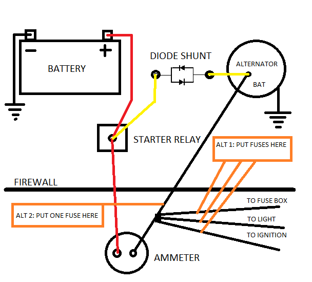
Made a wiring diagram to get some answer. The yellow is how i wonder the diode shunt goes and the orange is how i should in-line fuse the dash like you mentioned. Made two options for how to fuse the dash. Thanks for the help.
67Dart273
Well-Known Member
Be careful fusing the headlights. The headlight switch originally has two sources of power
1--A great big lead from the splice feeds directly to the switch which already has a breaker in/ on the switch.
2--Tail/ park/ dash lamp power comes from the tail lamp fuse
3--The other "little trick" is that dash lamp power comes OUT of the dash dimmer and then goes to the instrument fuse.
Since you are "into this" you might also consider headlight relays to relieve the strain on the light, dimmer switches, and again, bulkhead connector.
Also be careful where you mount such things as fuse links, breakers, and fuses, as they are degraded by high temp, AKA engine heat.
Rice Nuker
Let the Coal Roll!
Bill or 67, is there any equasion regarding the shunt application to the reading on the ammeter?
Is the ammeter reading like exponential or fancier? Or simply a percentage of actual? What is the shunt ratio?
The shunt if that is the correct term, is pretty great if a person could get a relatively accurate reading by reading the factory gauge (based on a formula).
Is the ammeter reading like exponential or fancier? Or simply a percentage of actual? What is the shunt ratio?
The shunt if that is the correct term, is pretty great if a person could get a relatively accurate reading by reading the factory gauge (based on a formula).
BillGrissom
Well-Known Member
Good idea that you are running separate 8 awg wires thru the firewall. That is known as the "fleet bypass", which the factory did for some cars like taxi and police. I would use just the single big fuse shown. You can put it either in the engine bay or under the dash, wherever easy to get to and won't get too hot. I wouldn't bother with the smaller individual fuses you show since I think all those circuits have fuses in the factory fuse box.
I 2nd 273's suggestion to add relays to take the load off the switches and bulkhead terminals, where possible. I wired a relay on the key switch ACC wire, so the switch just actuates the relay coil. I also use a relay for "blower high" position since otherwise those switches like to melt, and the 5-button climate switch in my 69 Dart was expensive. Under-hood, I have relays for headlights, AC compressor, ignition. I used a relay box from a 91-94 Jeep, which also replaced the factory relays (horn, starter). Many people wire individual relays for head-lights to get brighter lights, but probably not necessary if your switches and connectors are good, unless you install HID bulbs.
My prior posts give calculations for the ammeter diode bypass. The diodes act as "variable resistors". They have almost infinite resistance at low current flow, so shouldn't affect the ammeter reading at low current. As current increases, they conduct much more, shunting current around the ammeter direct to the battery to protect it. In my 65 Newport, I measured 0.75 V drop across my ammeter at max alternator output (~50 A, w/ no diode shunt). At that point, the diodes I used in my Dart (Schottky type) should conduct strongly. Tested in my Dart, the ammeter goes no more than 50% scale with full 12 V on the square-back alternator, but I tried only at idle. The way you show it wired is correct. The main design consideration is putting the diodes where they have a good heat sink, maybe either right on the alternator or at the battery. Power dissipated will be P = i * dV, where dV is the voltage drop which you use the charts in the diode datasheet. Expect ~50W max dissipation. Of course, insulate all exposed metal since at battery voltage.
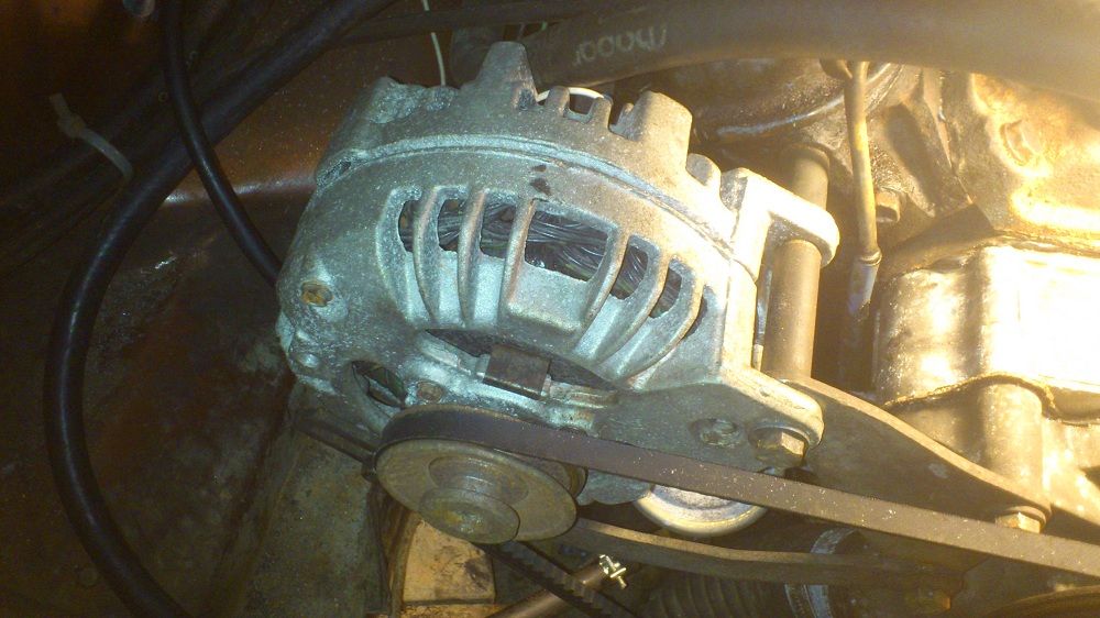
Since I got a 60A alternator, at least I think I have a 60A. It's mine alternator in the pic. As you suggest to use one single big fuse how big should the fuse be 60A if my alternator is really a 60A? I will put some relays as suggested too. But I need more info where to put those relays on bulkhead connectors, switches and so on. I have put relays to the headlights before so I can handle that. Thanks for the information guys.
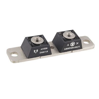
Another question Bill, will the MBRP400100CT diode you suggested in a other thread work as a shunt with my 60A alternator?
Another question Bill, will the MBRP400100CT diode you suggested in a other thread work as a shunt with my 60A alternator?
BillGrissom
Well-Known Member
I can't tell from the photo which alternator you have. The early ones have a round back, and were rated ~30A max though one could upgrade the stator windings to get ~60A and some probably came that way from the factory (police, etc). Later ones (~1972+) have a square-back with 3 diodes you can see hanging in the airflow. Those were used thru the 1980's. I had one on my 82 Aries which liked to vaporize its diodes once per year like clockwork. I think those were rated ~70A, and more importantly work better at low rpm.
Regardless, the MBRP400100CT diode is rated 200A in each leg, so should work for any alternator you install. Of course, the current rating is kind of incidental; diodes are really limited by heat so read the datasheet carefully. Your ammeter can pass an additional ~50A. The smaller Vishay VS-175BGQ045 diodes I put in my Dart are closer to the limit, which provides more signal on the ammeter at increased risk of damage. They were a bit less elegant to install, requiring soldering.
In answer to your final question on ammeter scaling, I don't recall that my 65 Dart's even has numbers on the scale. I recall that later cars had "70 A" or such at max scale. With the diode, it definitely will be a non-linear response, moving similar to factory on the low end and reaching a limit where the diode takes over and passes most additional current. It doesn't matter much to me since I just want to know "charging" or "discharging", without the dreaded "smoking". If I really want to know the alternator current, I have a Fluke clamp-on DC current probe. BTW, the diode in the reverse direction is to protect the ammeter when drawing from the battery. Ideally, the ammeter should be the only path to and from the battery. That is true for cabin loads, but transient underhood loads like horn and starter do not go thru it. Of course, any current going thru these new diodes will also bypass the ammeter.
I have searched what's the alternator generates and what I have found it is most likely a 60-70A. My car is a Swinger from 73. I also want to just see if it is charging or not, I'm not interested if it's accurate. Want to protect my A-body from fire as well too. As the diode has two legs should I use them both or just one? I found the MBRP400100CT diode on ebay so I'm going to order it soon.
KitCarlson
Well-Known Member
The battery side is a better filtered source of power than the alternator side.
KitCarlson
Well-Known Member
The alternator output is a rectified 3-phase AC signal. It has peaks and valleys. The battery is a low impedance storage device, that acts somewhat like a huge capacitor. The closer a electrical feed is to the battery, the more filtered and regulated it is. There are parasitic resistances in the system. The resistances result in voltage drops, so while nodes are connected by wires, the voltages will be different, and the differences increase with current flow. A scope may be used to view the voltages, and voltage drop and discover all this.
All this is important if you have electronic ignition, efi ....
Ignition manual for the Mallory Unilite says do not connect ignition suppy to alternator terminal is one example, the other is ECU feeds are supplied from a tap at battery terminal.
All this is important if you have electronic ignition, efi ....
Ignition manual for the Mallory Unilite says do not connect ignition suppy to alternator terminal is one example, the other is ECU feeds are supplied from a tap at battery terminal.
Rice Nuker
Let the Coal Roll!
To me there appears to be a common voltage drop across automotive aftermarket ammeter shunts?
So, on amazon there are a large number of automotive shunts with 75 millivolt drop.
A large variety of amperage handling ratings too.
There are also higher differential shunts on amazon.
Maybe a person could use one of these and get a consistent calculation correlation relative to their factory car ammeter?
Search shunt under automotive on amazon.
[ame="http://www.amazon.com/Amico-Ammeter-Current-Measure-Resistor/dp/B006Z954QA/ref=sr_1_3?s=automotive&ie=UTF8&qid=1364868748&sr=1-3&keywords=shunt"]Amico Amp Ammeter DC 300A 75mV Current Measure Shunt Resistor - Amazon.com[/ame]
Maybe the voltage drop is not significant enough to cause a good reaction from the factory gauge?
Possibly an option for sensitive DC electronics concerned with interference and AC noise, a DC-DC switching power supply to get clean power rather than directly off the auto +
Ive used these folks a few times and their products are reliable. I am not full of oscilloscopes so I dont know much about the power out other than it works for my telecom equipment long term.
They are friendly and will discuss applications and features over the phone too.
http://www.powerstream.com/su20-1212.htm
http://www.powerstream.com/dc12-12-8A-isolated.htm
67Dart273
Well-Known Member
You undoubtedly won't get much of a reading with an external shunt such as you describe. I have no idea what the meter movement is in the later Mopars, Ferds and GM external shunt meters, but they are MUCH more sensitive than the original Mopar "full current" meter
You might take that approach---adapt a different meter movement as some of us did the voltmeter conversion, AKA same idea, and go from there. But the factory "external shunt" stuff all of them simply used the harness itself for the shunt, and you can imagine, not very "calibrated."
In the case of Ford Rangers and the mid 70's Ferd pickups, example, I'm familiar with, these were pretty "numb" generally. That is, you get it and crank on the headlamps, and you have to REALLY look at the meter to see if it actually MOVED.
BillGrissom
Well-Known Member
You need to cut that diode pair in half, to make 2 separate diodes. Bolt them together with the arrows facing each way, as shown in your diagram. They nestle together nicely with the holes aligning. Install them at either end of your bypass wire (in series with the wire), but it needs to be somewhere with a good heat sink. Insulate all exposed wire w/ self-fusing silicone electrical tape.As the diode has two legs should I use them both or just one? I found the MBRP400100CT diode on ebay so I'm going to order it soon.
Sometimes it's hard to understand the whole point because I'm Swedish and that's why I don't understand everything because of the language. That's why I drawed this picture so you can see if I get it right Bill. I'm going to mount it nearby the battery think it's going to be a good spot. Thanks


BillGrissom
Well-Known Member
Yes, as 67Dart273 shows. Put the hole of each side over the tapped hole of the other. You could use the bolts that come with them, except I recall they are too short. I would take a photo, but didn't find them quickly looking in my box of parts. Once you get it, post a photo of them nestled together and I will confirm if OK.
As I mentioned, I haven't installed the MBRP400100CT diodes in my Valiant yet. I used the smaller diodes (100A?) of my first post in my 65 Dart. I haven't driven that car much yet so don't know if there is a problem with the design, but my ammeter does work and the diodes haven't gotten hot that I can tell. If they were to fail, it would probably be pretty quick. The big ones are safer (less heat) and easier to install at the same cost, but I haven't tested if the ammeter still reads well with them. In theory it should, since they shouldn't conduct hardly any current until the drop across the ammeter exceeds ~0.3 V and mine showed ~0.75 V drop at max current.
As I mentioned, I haven't installed the MBRP400100CT diodes in my Valiant yet. I used the smaller diodes (100A?) of my first post in my 65 Dart. I haven't driven that car much yet so don't know if there is a problem with the design, but my ammeter does work and the diodes haven't gotten hot that I can tell. If they were to fail, it would probably be pretty quick. The big ones are safer (less heat) and easier to install at the same cost, but I haven't tested if the ammeter still reads well with them. In theory it should, since they shouldn't conduct hardly any current until the drop across the ammeter exceeds ~0.3 V and mine showed ~0.75 V drop at max current.
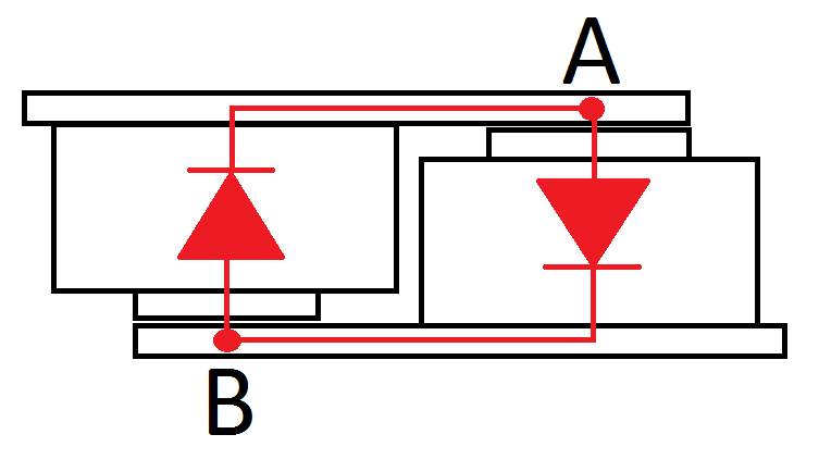
I made one more picture because I haven't ordered the diodes yet. It's frustrating, I just want to get a picture in my head how it's done. For me, it becomes confusing when arrows are drawn on the diodes. And does it matter which side you connect from the alternator to the connector or is it always one side that's A and the other always B? Bear with me. Thanks

67Dart273
Well-Known Member
Close. In your drawing, remove the top diode, and turn it upside down so that the point you marked "from alternator" is mating with the point you marked "hole"
The tab on the top diode will still be connected exactly as you have it, just upside down. In other words the connection between the two at top left in your drawing is unchanged except the top diode is now upside down. So when done you will have TWO identical connections to the two diodes.
I'm not good enough with photoshop to manipulate this, but they fit together one on top as below
Attachments
Now I understand, and it became obvious. I was fixed in how I would solve it and I misunderstood and read the diodes wrong. And I was locked that the symbols on the diodes should facing the same way when they were assembled together. It was the right and left symbol that I thought was 2 different diodes but the symbols only shows them together and if they cut in half they become single diodes. Thanks
-


