Red383
Well-Known Member
- Joined
- Jul 31, 2006
- Messages
- 114
- Reaction score
- 58
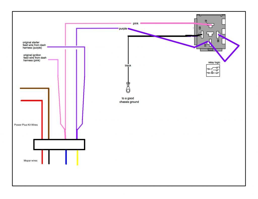
For those of you who used a Hotwire Auto harness on their new Hemi's, how did you get around the Pink wire "12 Volt Run and start". Chris at Hotwire told me it's easiest to use a start button, but I really would like to use the keyed ignition.
Can I wire a relay in to have 12v to the pink wire at key on and start position?
Thanks
Can I wire a relay in to have 12v to the pink wire at key on and start position?
Thanks