EZ Wiring Mini 20 Circuit Installation
Have not updated the progress because I have helped dad paint his house. It has not been slow on progress so far anyway just dont had time posting it here. Has not tied the harness yet so that's why everything hangs.
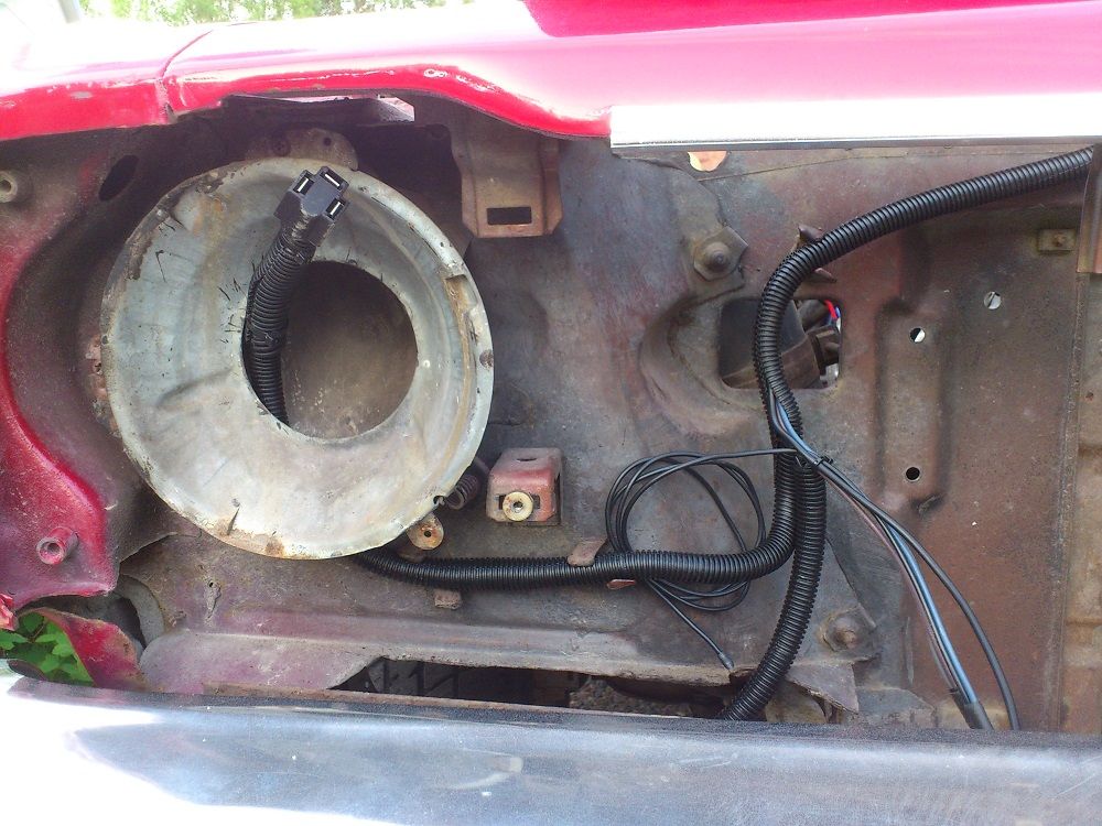
Side marker.
Mounted a maxi fuse holder and going to use the supplied fusible link also.
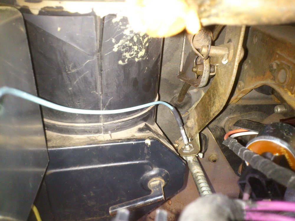
Using the fan power wire as the second power feed to the instrument light and park light on the light switch instead of splice the dimmer power wire.
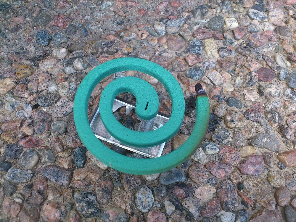
Used mosquito repellent to make it possible work outside. Great thing!
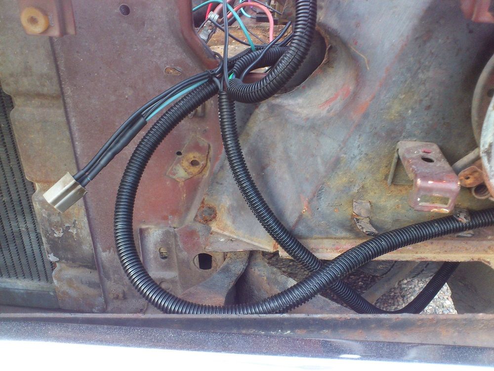
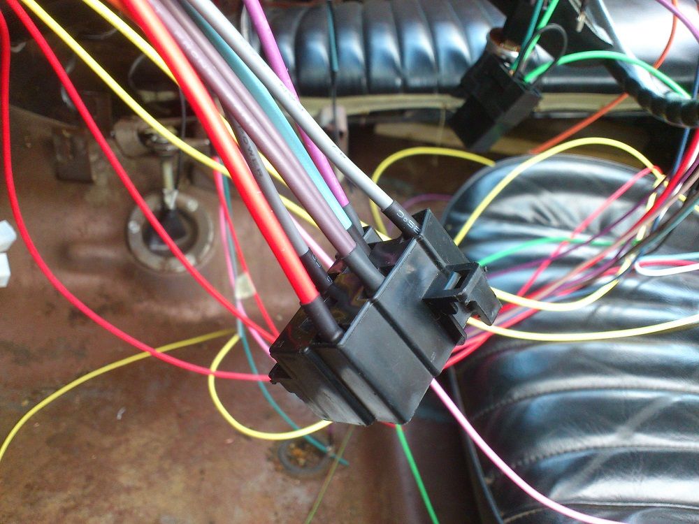
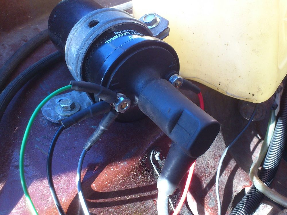
The black wire is from the ECU the green to the tach and the grey going to the fuel pump relay.
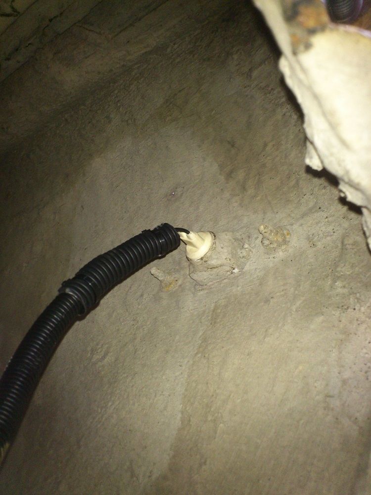
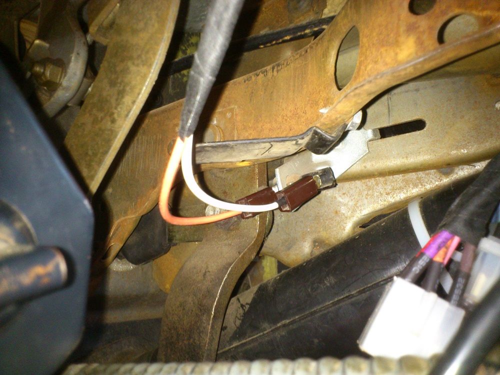
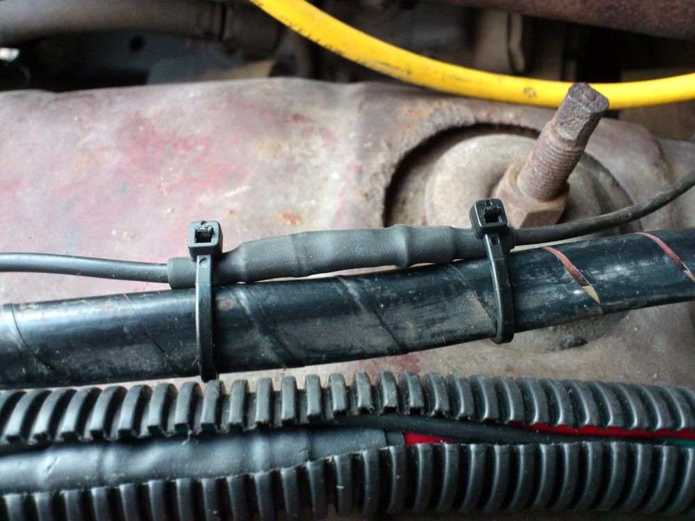
This is how I strain relief my butt connector like you mentioned goldduster318.
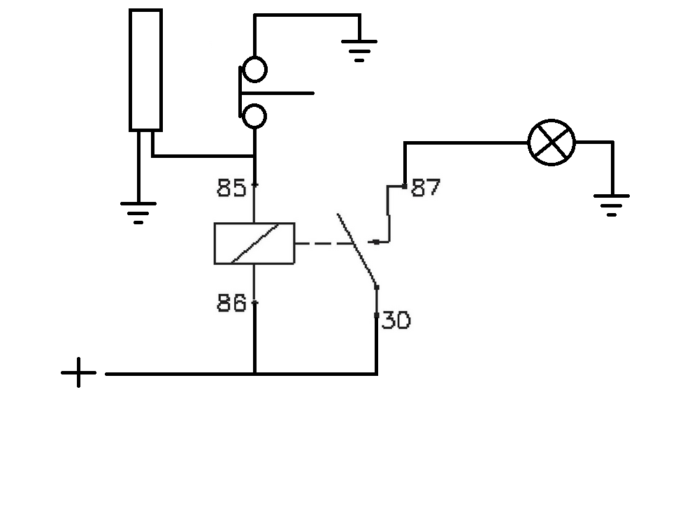
Since my time delay relay does not work I picked up a cheap light delay capacitor to power the key light. But since the light delay capacitor connects in series between the door switch and the lamp the key light would not work since it have no ground wire to connect in series with the light delay capacitor. Since the key light is grounded with a screw and have a yellow power feed wire, I came on with the light delay capacitor runs a relay that power the key light on and off with time delay when the door opens the circuit activate. This is a diagram I painted how it works.
Here is a film with the key light, time delay capacitor and relay in action. It actually worked for the first time I tried it. Proud that my idea turned out good to replacing a burned out time delay relay.
Have not updated the progress because I have helped dad paint his house. It has not been slow on progress so far anyway just dont had time posting it here. Has not tied the harness yet so that's why everything hangs.
Side marker.
Mounted a maxi fuse holder and going to use the supplied fusible link also.
Using the fan power wire as the second power feed to the instrument light and park light on the light switch instead of splice the dimmer power wire.
Used mosquito repellent to make it possible work outside. Great thing!
The black wire is from the ECU the green to the tach and the grey going to the fuel pump relay.
This is how I strain relief my butt connector like you mentioned goldduster318.
Since my time delay relay does not work I picked up a cheap light delay capacitor to power the key light. But since the light delay capacitor connects in series between the door switch and the lamp the key light would not work since it have no ground wire to connect in series with the light delay capacitor. Since the key light is grounded with a screw and have a yellow power feed wire, I came on with the light delay capacitor runs a relay that power the key light on and off with time delay when the door opens the circuit activate. This is a diagram I painted how it works.
Here is a film with the key light, time delay capacitor and relay in action. It actually worked for the first time I tried it. Proud that my idea turned out good to replacing a burned out time delay relay.