Voltage regulator upgrade? Keep frying voltage regulators with swap
FYI-
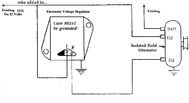
This is how I wired mine:
I have not tried to improve the ground since I've been having issues, though the firewall is sanded down to bare metal about a penny size behind one of the screws (for the voltage regulator to lay flat on).
FYI-
This is how I wired mine:
http://www.forabodiesonly.com/mopar/showthread.php?p=1969506503#post1969506503The voltage regulator simply turns the alternator on and off, no substantial current runs through the voltage regulator.
On a standard three wire alternator you have two field wires and one power wire, or output wire. With a modern 130 Amp Alternator with the right type of wire insulation you can run a wire as small as 6 Awg, most of the wire you are likely to buy at the auto-parts store may not have the high temp insulation so to be on the safe side run 4 Awg. wire, as even the poorest insulation on 4 Awg. is sufficient to carry 125 Amps.
Traditionally on a Mopar this single power wire would run through the bulkhead connector, through the amp meter, and then to the power distribution block. The full output of the alternator is passing through the bulkhead connector and through the amp meter. This arrangement was marginal in the 60s with 40-60 Amp alternators, it is a fire waiting to happen with a modern 130 AMP alternator.
You can run the wire a number of different ways. One possible way is to run a 4 Awg. from the alternator to the post on the battery. Another possible method is to run a 4 Awg. wire from the alternator to the power post on the starter and then another 4 Awg or even 2 Awg wire to your battery. (I would only recommend a 2 Awg wire on very large high compression motors, 2 Awg is a pain to work with and largely overkill).
As for wiring the alternator itself, your standard 60s era voltage regulator which was an electro-mechanical device has been replaced by a solid state device. (The ones in the sixties actually had something resembling points that you could visually watch open and close. Today, this turning on and off is done with a semi conductor and thus there aren't any moving parts which makes them more reliable.) If you happen to have the old 60s era voltage regulator fear not as no substantial current travels through the regulator it will work fine even on a 140 Amp alternator.
The key to understanding how a voltage regulator works is to see the voltage regulator as an on/off switch, it simply switches the alternator on and off. When 12 volts is supplied to one the alternator field posts, and the other field post is grounded the alternator charges. When the ground is removed the charging stops. So by grounding and un-grounding one of the field wires the alternator is able to cycle on and off rapidly to maintain a relatively constant 14-15 volts.
You'll see in the attached diagram that wiring your alternator is very simple. To one field post supply twelve volts when the key is in the on position. Attach the other field post to the regulator post marked field or F. Beware regulators MUST BE WELL GROUNDED (A lot of charging problems can be traced back to bad grounds). Finally, supply the regulator with 12 volts on the post marke I, when the key is in the on position.
IT DOESN'T MATTER WHICH FIELD GOES WHERE! One field gets 12 volts, one goes to regulator, it doesn't mater which.
Hope this helps,
Regards,
Joe Dokes

I have not tried to improve the ground since I've been having issues, though the firewall is sanded down to bare metal about a penny size behind one of the screws (for the voltage regulator to lay flat on).