Bench testing dash clusters ??

-

Princess Valiant

A.K.A. Rainy Day Auto
Joined
Dec 14, 2011
Messages
26,086
Reaction score
22,927
Location
Colorado
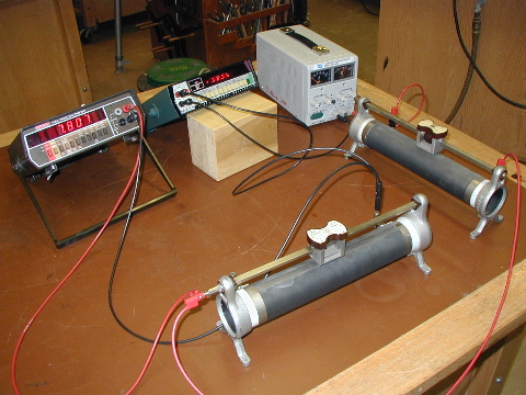
Is there a way to bench test a dash cluster.

I found a bunch of 70-76 and 70/1 type and I am fixin to sell them but I thought it would be nice to know if they work before I list them so the buyer will know what he/she is getting.
 
Of course. You want to check the gauges for some sort of accuracy, or just lights, or what?

http://www.forabodiesonly.com/mopar/showthread.php?t=179517

http://www.forabodiesonly.com/mopar/showthread.php?p=1970997882

With all the parts you probably have kickin' around you could probably just use a tank sender, and use an ohmeter beforehand to set it for the various test resistances. In fact you could mount it, and mark the arm for proper positions to test MT, 1/2 and full. That sender / resistor can be used to test oil and temp as well.

Of course you need a source of power. Best would be a 13.8--14V regulated bench power supply. You can buy them, in various forms, pretty cheap.
 
I use an old router transformer/power supply with a 12v- 1amp output and it works for all that stuff.

I bench test my mods before it goes back in the car with it.

I have a 5 gallon bucket full of them at various outputs but you can also find almost any voltage output transformers you want at a goodwill or thrift store.
 
And the speedo?
Cut a piece of speedo cable and chuck it in a drill motor.
I have used a dab of LPS1 on the drives.
Still working good after 100k.
 
Maybe you can bench race the different clusters and tell us which ones win... :burnout:
 
If you have an old round plug that goes into the factory gauges here is the colors for the wiring.

Fuel - Dark Blue
Dash lights - Orange
12V key on - Blue / White tracer
Turn signal LH - Lt Green
Turn signal RH - Tan
High beam - Red 18g
Brake - Blue/White tracer+ / Black 20g -
Purple - Water temp
Grey - Oil light
 
This is the setup I use for testing gauges. It is a 5 volt power supply made with a 7805 regulator and a precision variable potentiometer. I set the resistance I want with an ohmmeter then connect it up and check the reading. Using a variable potentiometer lets you slowly change the resistance and observe the meter movement.

Some things to note are. The meter will move slower than in a car, because you are putting in a constant 5 volts while a car is sending pulse width modified battery voltage. Don't get too concerned about accuracy, because every Instrument voltage regulator puts out a different voltage. Unless the car has an electronic IVR, it's just a piece of metal that gets hot and bends, there's no accuracy there.
 

Attachments

  • meter test 004B (800x600).jpg
    41.5 KB · Views: 240
This is the setup I use for testing gauges. .

I have a HUGE problem with that. ANYONE who can afford one of those fancy Panavises has way too much money to spend, LMAO!!!

On a serious note (and I don't recall off hand) be aware of the current they draw, IE the wattage rating you need for that resistor.
 
This is the setup I use for testing gauges. It is a 5 volt power supply made with a 7805 regulator and a precision variable potentiometer. I set the resistance I want with an ohmmeter then connect it up and check the reading. Using a variable potentiometer lets you slowly change the resistance and observe the meter movement.

Some things to note are. The meter will move slower than in a car, because you are putting in a constant 5 volts while a car is sending pulse width modified battery voltage. Don't get too concerned about accuracy, because every Instrument voltage regulator puts out a different voltage. Unless the car has an electronic IVR, it's just a piece of metal that gets hot and bends, there's no accuracy there.

What are the specs for the pot? I have a few that I use for Arduino projects. Well, that's when I used to tinker with that thing. I haven't in about a year.
 
What are the specs for the pot? I have a few that I use for Arduino projects. Well, that's when I used to tinker with that thing. I haven't in about a year.

This is my point. Many smaller pots don't have the required wattage. Even if you don't 'burn' the pot, the current through it during the test will most probably change the resistance, making your test somewhat inaccurate.


(Which reminds me of a story, LOL) Years ago a then friend and I were testing a big amateur radio amplifier. Unlike CB, amateurs are allowed 1500W out, and this amplifier had a little headroom over that. We were doing initial tests, but he didn't have an adequate "dummy load."

(50 ohm high wattage load to replace antenna)

So we were using a Heathkit dummy load "Cantenna" in a bucket of water for extra cooling, LOL

HeathkitCantenna.jpg


This thing was being operated at somewhere around 2KW output, and the tuning kept wanting to change. We could NOT figure out "whut." Then I looked down at the stinking, oily, steaming bucket of dummy load, and so we checked the resistance. The "should be" 50 ohm load had gone down I think to about 25-30 ohms!!!!!
 
JoesEdge and 67Dart273, I don't remember the specs on the potentiometer, but it is rated high enough to handle any troubleshooting I do. I wrote precision potentiometer in my write up, because that's what it takes to do accurate testing. That pot cost me about $30. I didn't want any Radio Shack/ching chang crap.
 
Ohm my goodness. I'm completely lost. Somewhere around resisting the potentiometer it all became greek. I'm going back to my coloring book!
 
Ohm my goodness. I'm completely lost. Somewhere around resisting the potentiometer it all became greek. I'm going back to my coloring book!

yea ...me too ...I see I opened a can of worms. But, no time like the present to master this and know even one more thing about our cars.


Cool.....what are you coloring ...any extra crayons for your buddies :D
 
Ohm my goodness. I'm completely lost. Somewhere around resisting the potentiometer it all became greek. I'm going back to my coloring book!

Don't overthink. Basically, the pot is nothing more that your tank sender......an adjustable resistance.

You WOULD need an accurate multimeter.........not at all difficult, special, or expensive nowadays (although I pretty much use Fluke, I have three or four of them)
 
yea ...me too ...I see I opened a can of worms. But, no time like the present to master this and know even one more thing about our cars.


Cool.....what are you coloring ...any extra crayons for your buddies :D

I got the BIG box of crayons.. plenty for everybody.. they gave me a helmet along with the crayons. Not sure what that's about...
 
Don't overthink. Basically, the pot is nothing more that your tank sender......an adjustable resistance.

You WOULD need an accurate multimeter.........not at all difficult, special, or expensive nowadays (although I pretty much use Fluke, I have three or four of them)

Thanks Del. That helps a little bit. Just get a little scared around all the big words.. 'Specially them electrical ones.. but I'm slowly picking up bits and pieces. Thanks for sharing your experience around here. It does help.
 
A "pot" or "potentiometer" get's it's name from "controlling potential". By accepted definition, a variable resistor "to be a pot" is three terminals........the two ends of the resistor, and the moving contact.

A pot can be used (as in this case) as a "rheostat" which is only a 2 terminal variable resistor

All you are doing, is sliding a contact along the resistor, until you reach whatever value you want

Here are some laboratory / demo pots. Nothing more than a resistor and a sliding contact

eo-01.jpg


Here's a great big high wattage "pot" because it has three terminals. If it only had two, like your fuel sender (the terminal and ground) it would be a "rheostat"

20-Ohm-150W-High-font-b-Power-b-font-Ceramic-Rheostat-font-b-Variable-b-font.jpg
 
Confuscious say: Man who stand on toiled is high on pot...
 
-
Back
Top