Squareback vs round back alternator?

-
I'm going to throw this out there. Maybe it is just fine and functioning as expected?

If you raise the engine RPM does the fluctuation level out?

Rebuilders are notorious for putting a 70mm dia or 76mm dia pulley on alternators that should have a 63.5mm dia pulley. The seemingly small dia change makes a huge difference in alternator shaft speed and the output at 1000 rpm shaft speed vs 1500 or 2000 rpm shaft speed can be the difference between charging and not charging.

Diameter, diameter, diameter, alternator pulleys

You mentioned with more accessories turned on it levels out.

I agree with Mattax. Get familiar with the workings of the old stuff before you attempt to make changes.

The master tech videos are really good at explaining how things work.

Mymopar.com has a lot of them

Don't get too hung up on the year and the car. Early 60s work the same as late 60s.

Welcome aboard and good luck to you.

It's a 68 mm pulley on this alt.
I will check all that when the ign system is complete again.
 
Last edited:
Yes. Usually only the part number. Specs will be in your shop manual.
The most important part to find new old stock will be the distributor points and condensor.

I can check that against new 1960s shop manuals.

View attachment 1715890184

Other end of repair positive wire should connect to ballast resistor. Where that is located, I don't know.

The ballast resistor is missing on this car. So I ordered one and once it's installed on the right place we'll check with the tests you suggest earlier in this thread.
 
If I understand right the additional relay reduces ballast in J2 wiring to the dash and guides the biggest charing load in the eng compartment wiring, right?
Actually I don't see the reason for the new relay. All those connections and wire could introduce more resistance.
The current load draw is actually very low. 2 to 3 amperes for ignition coil and 1 to 3 amperes for the alternator field.
So maybe as much as 6 amps.
Only reason I can think of for the new relay was resistance in the key switch. But if so, then that should be fixed anyway.
 
I think that ballast resistor will work OK. make sure it measures what they claim.
From the 1960 Dodge shop manual
upload_2022-3-17_11-48-26.png


1965 Plymouth Shop manual
upload_2022-3-17_11-52-8.png


So .5 to .6 Ohms is probably correct match.

The older orignal ballast resistors are made with a metal bracket for mounting. Othewise the shape is same.
 
Actually I don't see the reason for the new relay. All those connections and wire could introduce more resistance.
The current load draw is actually very low. 2 to 3 amperes for ignition coil and 1 to 3 amperes for the alternator field.
So maybe as much as 6 amps.
Only reason I can think of for the new relay was resistance in the key switch. But if so, then that should be fixed anyway.

Exactly, each connection produces resistance.
On top the trigger wire 85 for the relay is clamped right on IGN 2 wire at the connector of the ign switch. And with this "current thiefs" as we say here in Germany it increase resistance as well because you cut some single "veins" (?) of the copper wires itself.
I ordered a new ign switch as well, let's cross the fingers for functionality.
Maybe I'm too picky here but I like the things done the right way.

How you call this professional part?
upload_2022-3-17_17-3-9.png
 
I think that ballast resistor will work OK. make sure it measures what they claim.
From the 1960 Dodge shop manual
View attachment 1715890461

1965 Plymouth Shop manual
View attachment 1715890462

So .5 to .6 Ohms is probably correct match.

The older orignal ballast resistors are made with a metal bracket for mounting. Othewise the shape is same.

As for the ballast resistor I cross checked your number #2095501 and the one I have in the Valiant book #1889545 and it turns out they have both the same values. Except in my book the resistance isn't shown.
IMG_20220317_170851 (1).jpg
 
As for the ballast resistor I cross checked your number #2095501 and the one I have in the Valiant book #1889545 and it turns out they have both the same values. Except in my book the resistance isn't shown.
View attachment 1715890478
Thank you. I think you are OK. Maybe attachment method changed.
@halifaxhops may have more complete cross reference.
 
If I understand right the additional relay reduces ballast in J2 wiring to the dash and guides the biggest charing load in the eng compartment wiring, right
All the relay does is feeds the voltage regulator with 100% battery voltage. Otherwise you could have a voltage drop at every connection and switch along the path from the battery to the voltage regulator, giving the voltage regulator a false battery reading causing it to tell the alternator to charge at a higher voltage.

(After this is all done I would love to know how different the older European cars are as compared to our A bodies. )
 
It's a 68 mm pulley on this alt.
I will check all that when the ign system is complete again
That is probably equivalent to the 70mm

Because the pulley swap is a rather involved process requiring a press and disassembling the alt. I would just live with it at this point.
 
feeds the voltage regulator with 100% battery voltage
Battery
169071-12cf868074d2efacc74af921ebf86bb7-gif.gif


System
thumbs_up-gif.gif


The regulator gets voltage from whatever it is closest too. When the engine is running, most of the time its not really 'battery' voltage.
We unfortunately commonly use 'battery' when we mean power from either battery or alternator. Just like we say '12 Volt system' when its regulated to run around 14 Volts.
So I knew you meant.
drivin-gif.gif
 
All the relay does is feeds the voltage regulator with 100% battery voltage. Otherwise you could have a voltage drop at every connection and switch along the path from the battery to the voltage regulator, giving the voltage regulator a false battery reading causing it to tell the alternator to charge at a higher voltage.

(After this is all done I would love to know how different the older European cars are as compared to our A bodies. )

Alright, thanks for your explanation. And yes, after this is done I can send some pictures from recent projects were we repaired or updated electrical system on older french cars like Citroen DS.
 
If the key switch has poor connections, then I would wire a relay this way.
The other fuses could be used for headlights.
upload_2022-3-18_8-47-35.png
 
If the key switch has poor connections, then I would wire a relay this way.
The other fuses could be used for headlights.
View attachment 1715891242

Thank you for the drawing. The red wire (87) from the relay going to the fuse box?
It seems the parts coming from NY this Monday already, will replace the key switch and install the ballast resistor and perform the resistance and voltage measurements.
 
The red wire (87) from the relay going to the fuse box?
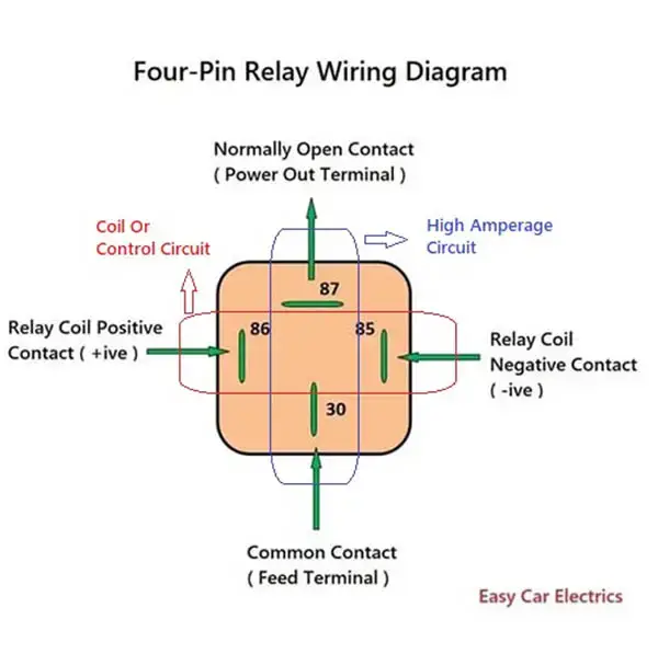
Going by the standards I find on the internet, 87 is power out when the relay is turned on.
Something like this.
Automotive-Relay-Diagram.jpg


The relay may be totally unneccesary with a new key switch.

It might still be useful for headlights and fog lights.
Headlight wiring and switches on the 1960 model are likely different than later A-bodies and B-bodies.
On the later A-bodies, there was a single pair of 40 Watt headlamps. The wiring path was long, and used relatively small wires. So the circuit does not fair well when higher wattage replacement lamps are used. In US this was 6012 bulbs being replaced by 6014, and of course in more recent years H4 type lamps.

We see in the 1960 main circuit wiring, that power from the alternator connects first to the headlight switch. So that is one difference. I'm sure we will find others.

----
Using the maxi fuse in the battery line A1 is a great idea.
 
Last edited:
Hello everyone,

the parts have arrived this Wednesday from the US. So I have started to install and wire it the way the workshop manual showed incl. a ballast resistor. The charge voltage is perfekt with new electronic Vreg, it moves between 13,8 V in idle and up to 14,4 V above idle, no fluctuations anymore.

I have installed as well new spark plug wires, a new coil, condenser, spark plugs, ignition switch. The engine fires right up and seems stable so far, a following test drive will show more.

Still a bit chaotic the wiring but it's just for test purposes ...
It took me a while to find the IGN1 wire, it fed a new relay for the horn combined with a second wire going to the positive contact at the ign coil. I understand the purpose of that modification and will care about the horn later, first putting the ignition and charge system into original specs.
Moreover wire IGN2 and 1 were interconnected right behind the ignition switch. There were no ballast resistor before installed so it didn't matter, all available current went to the coil ... Maybe the old coil had an internal ballast resistor?

Old coil:
primary (- -> +) = 1,3 Ohms
secondary (- -> 4) = 9,64 kOhms

new coil:
primary = 1 Ohm
secondary: = 8,8 kOhms


On the lower contact of the ballast resistor I installed IGN 1 wire and IGN from the Vreg IGN. On the upper contact is the ign coil positive wire and IGN 2 wire.

Coming to the voltage for the ignition coil. At idle I measured ~ 12,8 V, above idle up to 13,7 V. Does anyone know what should arrive there? The new coil is a 12 V and it's written "use ext. ballast resistor" (no further specs). While ign switch is at IGN1 it should not exceed 12 Volts that much, right? With the old setup and defektive Vreg there were up to 17 Volts ...

Also I have noticed the AMM just moves a bit to D(echarge) while starting and while the engine is running and the ALT is charging it moves up 2 mm into C(harge) also when all lighting and other users are ON. With the old setup the AMM pointer was very nervous high into C (faulty Vreg....) Note: I just recharged the battery. I'm going to measure current and voltage drop once I figured out if the voltage the the coil + is correct or incorrect and eventually further mods.

IMG_20220324_154915.jpg


Old plugs left: Champion RN14YC, new at the right Denso W14EXR-U
I couldn't get the Champion within a few days, so I cross checked with the WS manual ref no. "AG 42" and the Denso plugs were recommended. Shorter body, resistance the same. What do you think, any recommandations?

IMG_20220324_083523.jpg


The new horny relay. On the empty conact was IGN1 and a secon wire going to the coil +

IMG_20220324_155052.jpg


New ignition coil

IMG_20220324_155134.jpg

upload_2022-3-24_16-57-10.png
 
Last edited:
Looks like you are on your way.

Just a point.

One side of the ballast resister should go to the coil. The other side should go to ign 1 and the ign1 side should have battery voltage ( 12 to 15v) with the key in the run position

The coil side should have much less like 5 to 8v depending on the rpm.

The ign2 wire should have approximately 8 to 12 v ONLY while cranking (key in the start position).

The ign2 wire should be attached to the same side of the ballast resister that the coil is attached to.

I assume you seperated the ign1 and ign 2 wire behind the key switch.

Thanks, yes, it's going there slowly but steady.

Yes, I separated the ign1 and ign2 wires. Correct, right?

The way you explained the contact assignment on the ballast resistor is exactly the way the WS manual shows and I did it that way.
1. upper contact: coil + and IGN2
2. lower contact: IGN 1 and IGN from Vreg

Voltages measured

upper contact (coil + and IGN 2)
Engine off, key in RUN pos.: 7,5 Volts (!)
Engine cranking: 10 Volts
Engine idles and higher rotations: up to 13,8 Volts

lower contact (IGN 1 and IGN from Vreg)
engine off, key in RUN pos.: 12 Volts and dropping slowly
Engine idles and higher rotations: up to 14,4 Volts

Should I try a ballast with a higher resistance or do I miss something in that puzzle?


IMG_20220324_175746.jpg
 
Last edited:
Also I have noticed the AMM just moves a bit to D(echarge) while starting
This is correct. Power to the starter solenoid and coil goes through the ammeter and key switch.
upload_2022-3-24_15-34-56.png

Current draw for each item is approximate as I do not have a 1960 specific manual or Sun card. My point is to illustrate the current paths.

The voltage at the coil during start should be very close to the battery voltage during start.
Battery voltage during start should be at least 9.4 Volts. I don't see any reason why 1960 would be much different.

nd while the engine is running and the ALT is charging it moves up 2 mm into C(harge) also when all lighting and other users are ON.
If the lighting and accessories are still wired to draw power from the battery side of the the ammeter, that is what you are seeing on the ammeter.
Otherwise you should only be seeing battery recharging on the ammeter.
As far as the voltage measurement. I suspect this will depend on how the meter measures the cycling as the points open and close.
Votlage drop across the resistor for a steady flow (points closed) is current multiplied by resistance. Assuming 3 amps through the coil 12.2 Volts is about right.
upload_2022-3-24_15-54-48.png


Ammeter will show battery charging. Illustration shows 6 amps but it will actually range from 10 to 20 amps after starting to 0 amps after a few minutes of charging.
upload_2022-3-24_16-14-48.png

Any additional items attached to the battery positive terminal will make it appear as if the battery is charging when they are turned on.

Old plugs left: Champion RN14YC, new at the right Denso W14EXR-U
I couldn't get the Champion within a few days, so I cross checked with the WS manual ref no. "AG 42" and the Denso plugs were recommended. Shorter body, resistance the same. What do you think, any recommandations?
The nose doesn't look much shorter. Try it - see how it runs.
 
Last edited:
Old coil:
primary (- -> +) = 1,3 Ohms
secondary (- -> 4) = 9,64 kOhms

new coil:
primary = 1 Ohm
secondary: = 8,8 kOhms
New coil has lower resistance in primary so will draw more current, although I think that when connected to power it is also effected by the inductance.
I would stay with the old one and keep the new one as a spare.

We saw in the FSM that 3.0 amps was for when the engine was off, points closed.
1.9 amps running at idle (500 - 600 rpm?) So you can do the votlage drop math for that if you want.
 
Last edited:
A bit late chiming in. First verify that you require the ballast resistor. Many people bypass it when upgrading the ignition. I didn't see where you opened the distributor cap to verify there are points. Someone may have retrofit a Pertronix Ignitor electronic ignition under the cap. Those were sold even back in the 1990's. Another is the Crane Cams XR700 optical pickup wheel, but would then have an external box. If it has points ignition and you ran it without the ballast, so the ignition coil + got full 12 VDC all the time, the coil would soon get very hot (enough to smell its paint melting). It the car had been running fine, that suggests you don't have a points ignition. Also, whoever wired the relay was smart so unlikely they would have eliminated the ballast without good reason.

The relay is good to give full IGN power to underhood consumers. I put one in all my 1960's Mopars (via fuse/relay box from 1990's Jeep). The terminal numbers are standard German DIN seen on all Bosch-style relays (even today). 30 is usually power in, but sometimes input on 87 (normally the output). I see 85 commonly for coil-, but polarity doesn't matter unless there is an internal diode across the coil (86 & 85). Since IGN and IGN2 are jumpered together (no ballast), IGN2 works fine to activate the coil. Even with the ballast you added, it may still work since the IGN2 wire will run ~8 VDC (key in "run") which should still be enough for coil+ to activate the relay. Note: when I say "coil" in this paragraph I mean the coil inside the relay, not the "ignition coil".

Re alternator, as stated you can run either the original roundback or squareback, using either the older high-side switching (one brush grounded) or low-side switching (2 field wires to alternator, one being IGN output from relay). You can wire a squareback to serve as a roundback (just ground one brush, doesn't matter which one).

Re the voltages you measured in post 72. I suspect you don't have points in the distributor (pop off the cap and show a photo). That is because at "ignition coil +" you measure 13.8 VDC (engine running). If you had points (with proper dwell set), you should measure ~8 VDC (or less). That is the whole purpose of the ballast, to reduce the average voltage at the coil (gets full 12 VDC when cranking via IGN2 via key switch). Whatever is switching the coil on and off is more efficient than points, so likely an electronic ignition. You don't need to restrict its voltage (except if an old 1970's Mopar ECU). It only drops 0.6 V across the ballast (14.4 - 13.8). The readings at IGN are "about right". Should be 12.6 VDC with engine off if battery is fully charged and ~14.3 VDC with engine running if alternator and Vreg are working fine. I am confused by your "IGN 1 and IGN from Vreg". The factory drawings don't have an "IGN 1", just an "IGN" and "IGN2". Also, IGN flows to Vreg not from it. Vreg is a consumer of IGN power and also tries to control it (via the alternator output).
 
-
Back
Top