Temp gauge/fuel gauge trouble shooting
To ACTUALLY test these you need to do an "end to end" inspection and test.
Some preliminaries as these girls are old and can be corroded, loose, etc.
1...The harness connector pins on the pc board can be loose. Clean, flux with a rosin flux, and solder using proper electronic oriented lead/ tin solder
2...The finger/ contacts that the IVR plugs into (non ralley cluster) can be making poor contact with the PC board traces. Clean flux and solder bridges across. "Work" the IVR in/out several times to scrub the connections
3...The fake nuts on the gauge studs can lose good contact with the pc board. loose/ tighten several times to scrub the board clean. Consider using real nuts, ad maybe star washers
4...I would not screw with the IVR if it is a oem electro-mechanical one. Just buy an electronic replacement such as RTE
5...Find 1 or 2 common ground screws on the board/ cluster, add a grounding pigtail, and bolt that to the column support or dash frame. The cluster is OEM "poorly grounded" via the cluster assembly mounting nuts.
Now, rig the thing on the bench with a 12V battery, fully charged, or a 14V bench supply, not a charger, to the proper harness pin and ground.
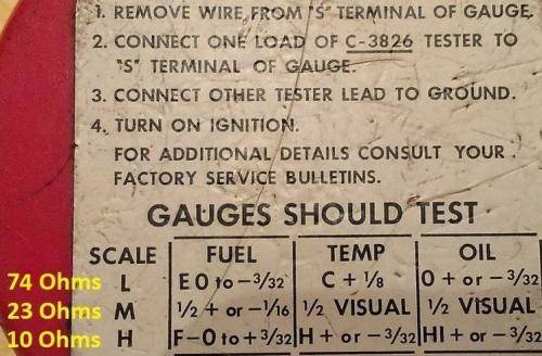
You need either some test resistors, or a variable one that you can adjust to an ACCURATE ohmeter. An old but useable fuel sender will work. Substitute the proper resistances for the senders and note if they read correctly. The meter movements are the same Here are the test resistances:
This is a third party tester that mimicks the OEM one shown in the shop manual. It is a 3 position switch that selects the 3 test resistances, for low, mid range, and "hot" or "full"
To ACTUALLY test these you need to do an "end to end" inspection and test.
Some preliminaries as these girls are old and can be corroded, loose, etc.
1...The harness connector pins on the pc board can be loose. Clean, flux with a rosin flux, and solder using proper electronic oriented lead/ tin solder
2...The finger/ contacts that the IVR plugs into (non ralley cluster) can be making poor contact with the PC board traces. Clean flux and solder bridges across. "Work" the IVR in/out several times to scrub the connections
3...The fake nuts on the gauge studs can lose good contact with the pc board. loose/ tighten several times to scrub the board clean. Consider using real nuts, ad maybe star washers
4...I would not screw with the IVR if it is a oem electro-mechanical one. Just buy an electronic replacement such as RTE
5...Find 1 or 2 common ground screws on the board/ cluster, add a grounding pigtail, and bolt that to the column support or dash frame. The cluster is OEM "poorly grounded" via the cluster assembly mounting nuts.
Now, rig the thing on the bench with a 12V battery, fully charged, or a 14V bench supply, not a charger, to the proper harness pin and ground.
You need either some test resistors, or a variable one that you can adjust to an ACCURATE ohmeter. An old but useable fuel sender will work. Substitute the proper resistances for the senders and note if they read correctly. The meter movements are the same Here are the test resistances:
This is a third party tester that mimicks the OEM one shown in the shop manual. It is a 3 position switch that selects the 3 test resistances, for low, mid range, and "hot" or "full"