You are using an out of date browser. It may not display this or other websites correctly.
You should upgrade or use an alternative browser.
You should upgrade or use an alternative browser.
Inside a FBO control box
- Thread starter minty
- Start date
-
bad440
everything,all the time..
damn wish i had an orange box to compare....
TrailBeast
AKA Mopars4us on Youtube
You are lucky that crap came out in one peice.
Usually it only comes out in little chunks.
Usually it only comes out in little chunks.
longarm
Car sold back to original owners
Its not about what it looks like,
its about how it performs.
You could possibly repair that unit since
you were able to remove the backing.
its about how it performs.
You could possibly repair that unit since
you were able to remove the backing.
67Dart273
Well-Known Member
Its not about what it looks like,.
I've been around electronics for a very long time and I say...............
So you can have the huge piles of cold solder if you want, that's OK............
jos51700
Green Bearing thread connoisseur
Looks alot like the standard box, with an FBO sticker (Except it doesn't have the driver transister in corner).
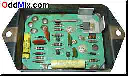
I'm betting it's a parts-store stocker that some sucker stuck a sticker on.
I'm betting it's a parts-store stocker that some sucker stuck a sticker on.
KitCarlson
Well-Known Member
Quick put some black goop back over it, it is making me sick ") .
.
The gobs of solder are horrible. I think there are loose solder balls near the top.
.The gobs of solder are horrible. I think there are loose solder balls near the top.
longarm
Car sold back to original owners
I've been around electronics for a very long time and I say.QUOTE]
As have I and this is pretty common.
You can't see well enough to make any
assessment of the quality of the components.
The soldering looks like it might have been done
by hand which is not uncommon either.
If you believe its a cold solder joint, resolder
and try it again.
As for total quality you'd have to make that accessment
for yourself and act accordingly.
Your other choice is a single chip like the HEI which
in my opinion is hard to beat.
You could buy the MSD and see whats in their box.
If you like you can google it or I can do it for you.
mopar head
Well-Known Member
I just finished gutting an old one I replaced that was intermittant bad.damn wish i had an orange box to compare....
Mine is/was the same way, One interesting point is where there is the large gob that grounds the board to the case seemed it was a cold joint, probably causing my intermittant problem?Quick put some black goop back over it, it is making me sick
The gobs of solder are horrible. I think there are loose solder balls near the top.
I put a red arrow pointing to it in #2 pic.
The potting material had a bunch of crystals added, probably desiccant?
Seems alot different than the others
Attachments
longarm
Car sold back to original owners
jos51700
Green Bearing thread connoisseur
That one with the arched PCB looks familiar. Isn't that the one that they found out were being counterfeited, and it just has some stock in-distributor ignition module wired in?
Edit, not it, but close:[ame]https://www.msdignition.com/uploadedFiles/MSDIgnitioncom/speedway_Ill_conterfeit_feb_12_lr.pdf[/ame]
Edit, not it, but close:[ame]https://www.msdignition.com/uploadedFiles/MSDIgnitioncom/speedway_Ill_conterfeit_feb_12_lr.pdf[/ame]
longarm
Car sold back to original owners
Crane
MSD
ProComp
http://www.msextra.com/
[ame]http://web.tiscalinet.it/giordy/ECU/msd6a_02.pdf[/ame]
http://www.google.com/patents/US4131100
MSD
ProComp
http://www.msextra.com/
[ame]http://web.tiscalinet.it/giordy/ECU/msd6a_02.pdf[/ame]
http://www.google.com/patents/US4131100
BillGrissom
Well-Known Member
You are lucky to have a clean enclosure to work with. I expect the potting popped out in one piece because it wasn't the correct material. Maybe they used cheap silicone caulk. I also work with electronics and agree that those solder joints are very poor. It is getting hard to hire dependable peasants in China today. At least they did use a quality film capacitor (yellow), though only 1 vs the standard 2. It would be interesting to see the other side, where I expect the power transistor is pressed against the case for heat sink.
I would pull the board and wire-in a 4-pin HEI module (~$10 ebay). Others have done so, and I think you can find instructions here. That would give you a much better ignition, while keeping the Mopar look, and leave your factory harness unmolested. Jumper the 2 ballast terminals together (0.5 ohm side if a dual ballast, you won't need the 5 ohm side). You can then run a hotter coil, like an e-core, and open your spark plug gaps to ~0.045".
That photo of the MSD box with the in-distributor ignition module is hilarious. Did an owner do that, or was that a clever Chinese copycat solution?
Now that right there is funny. I don't care who you are.
I've been around electronics for a very long time and I say...............

So you can have the huge piles of cold solder if you want, that's OK............
TrailBeast
AKA Mopars4us on Youtube
That photo of the MSD box with the in-distributor ignition module is hilarious. Did an owner do that, or was that a clever Chinese copycat solution?
Thats a Pertronix unit that someone installed inside the box so it looked factory.
I have already built two 4 pin HEI factory boxes like this so far.
Attachments
That looks like an unsuspecting Standard Ignition LX101.
TrailBeast
AKA Mopars4us on Youtube
That looks like an unsuspecting Standard Ignition LX101.
From the top it does.
The only giv away from the top is the two screws stick up a little higher because the Diode mounts they held is gone from the inside.
The Diode you see on the top is just for looks now.
KitCarlson
Well-Known Member
Just to put things in more modern perspective, this is what I would use, no external ballast required.
Included:
chip for Variable Reluctance trigger (actually for 2 triggers)
IGBT ignition driver
Automotive rated voltage regulator for 5V
Current limit control
Misc. caps and resistors
I am more into Hall and Optical than VR, so no plans to make a kit.
Included:
chip for Variable Reluctance trigger (actually for 2 triggers)
IGBT ignition driver
Automotive rated voltage regulator for 5V
Current limit control
Misc. caps and resistors
I am more into Hall and Optical than VR, so no plans to make a kit.
Attachments
TrailBeast
AKA Mopars4us on Youtube
Just to put things in more modern perspective, this is what I would use, no external ballast required.
Included:
chip for Variable Reluctance trigger (actually for 2 triggers)
IGBT ignition driver
Automotive rated voltage regulator for 5V
Current limit control
Misc. caps and resistors
I am more into Hall and Optical than VR, so no plans to make a kit.
What purpose does the penny serve?
KitCarlson
Well-Known Member
Size reference.
TrailBeast
AKA Mopars4us on Youtube
Size reference.
I know, I was messin with ya.
I was going to say that a copper plate would look a lot more professional than a penny for a heatsink.
Thats a Pertronix unit that someone installed inside the box so it looked factory.
I have already built two 4 pin HEI factory boxes like this so far.
Trailbeast do you got any more pics of the 4-pin HEI in a Mopar ECU case? Planning to do one my self.
KitCarlson
Well-Known Member
I know, I was messin with ya.
I was going to say that a copper plate would look a lot more professional than a penny for a heatsink.
With proper dwell control, not much heat sink required. That could be done with a chip the size as the 8 pin one.
Copper pennies, not since before 1982
. Copper is heavy, real race cars use aluminum .I was going to use a dime, but did not want it to get political, seems most like Lincoln.
Nothing wrong with HEI, similar to my bunch of parts, but already packaged. Much better than OEM box or the sick photos of MSD guts.
-


