I want to replace my ammeter with a sunpro volt meter for a factory look (well almost). I was going to solder the old ammeter wires together and try to upgrade my under the hood charging system wires. What is the best way to send power to my instrument cluster when I unhook the ammeter? Is tehre any other things i need to upgrade or chane with this modification? I looked at the MAD electrical page to add in the under the hood modifications. I also plan on making the denso upgrade as well to the alternator.
You are using an out of date browser. It may not display this or other websites correctly.
You should upgrade or use an alternative browser.
You should upgrade or use an alternative browser.
Install volt meter in place of ammeter wiring question
- Thread starter lee g
- Start date
-
daredevil
Well-Known Member
You already found the mad diagrams. They are what I used.You didnt mention what you were working on. If we knew we could be more help.
Just remove black & red wires from amp meter, bolt them together with a short bolt & lock washer, and tape them up using # 33 3M electrical tape, not the cheap junk that unravels after two weeks. This method affords one to be able to easily bring back dash to original condition in the future, and beats the heck out of under dash soldering.
67Dart273
Well-Known Member
You do NOT need to make other changes to your wiring "to power the instrument cluster" or anything else. FUNCtionally all you need to do is follow the MAD article, and as posted above, connect the ammeter wiring.
BUT WHILE you are at it, it is EXTREMELY important to check your bulkhead connector and repair it as necessary.
(While the MAD article reduces much of the current through the bulkhead, it STILL must have a power feed into the interior, AND ignition, headlights, and other circuits OUT of the bulkhead)
ALSO check the voltage drop THROUGH the bulkhead to important circuits.
These include headlights and the switched ignition circuit
The path, for example, in the ignition circuit is---
battery,-- fusable link,-- through the bulkhead,-- through the ammeter circuit, --the ignition switch connector,-- through the switch-- and back OUT the ignition switch connector--and back OUT the bulkhead to the "dark blue" (normally) switched ignition wire which supplies your ignition, regulator, the alternator field on 70/ later vehicles, electric choke if used, and I believe the idle solenoid and distributor solenoid if used.
TO CHECK this circuit for drop, do the following
If you have a breaker point distributor, make sure the points are closed. Turn the key to "run" with engine off. Put your meter leads on the coil negative and ground. IF the voltage is close to battery, the points are open. Bump the engine until the voltage goes very low. The points are now drawing current.
NOW put your probes as follows: One directly on the battery positive post, and the other on the regulator IGN terminal, or the ballast resistor "key" side connection
What you are hoping for is a VERY low reading. Anything over .2V (two TENTHS of a volt) is getting a little high, and anything approaching or over 1/2 volt is WAY too much.
The higher this reading is, indicates some bad connection in the circuit path above.
(This is part of the reason that many of us use headlight relays. On my 67, I used an underhood relay/ fuse box out of a Voyager. I used the relays in this box to run ignition, alternator field/ regulator circuit, and two relays for the headlights, another for the fuel pump.)
Before I did a partial rewire of my 67, there was a ONE VOLT drop in the ignition circuit.
(This drop ALSO causes a one volt overcharge at the battery, because the regulator "thinks" the battery is low.)
You do NOT need to make other changes to your wiring "to power the instrument cluster" or anything else. FUNCtionally all you need to do is follow the MAD article, and as posted above, connect the ammeter wiring.
BUT WHILE you are at it, it is EXTREMELY important to check your bulkhead connector and repair it as necessary.
(While the MAD article reduces much of the current through the bulkhead, it STILL must have a power feed into the interior, AND ignition, headlights, and other circuits OUT of the bulkhead)
ALSO check the voltage drop THROUGH the bulkhead to important circuits.
These include headlights and the switched ignition circuit
The path, for example, in the ignition circuit is---
battery,-- fusable link,-- through the bulkhead,-- through the ammeter circuit, --the ignition switch connector,-- through the switch-- and back OUT the ignition switch connector--and back OUT the bulkhead to the "dark blue" (normally) switched ignition wire which supplies your ignition, regulator, the alternator field on 70/ later vehicles, electric choke if used, and I believe the idle solenoid and distributor solenoid if used.
TO CHECK this circuit for drop, do the following
If you have a breaker point distributor, make sure the points are closed. Turn the key to "run" with engine off. Put your meter leads on the coil negative and ground. IF the voltage is close to battery, the points are open. Bump the engine until the voltage goes very low. The points are now drawing current.
NOW put your probes as follows: One directly on the battery positive post, and the other on the regulator IGN terminal, or the ballast resistor "key" side connection
What you are hoping for is a VERY low reading. Anything over .2V (two TENTHS of a volt) is getting a little high, and anything approaching or over 1/2 volt is WAY too much.
The higher this reading is, indicates some bad connection in the circuit path above.
(This is part of the reason that many of us use headlight relays. On my 67, I used an underhood relay/ fuse box out of a Voyager. I used the relays in this box to run ignition, alternator field/ regulator circuit, and two relays for the headlights, another for the fuel pump.)
Before I did a partial rewire of my 67, there was a ONE VOLT drop in the ignition circuit.
(This drop ALSO causes a one volt overcharge at the battery, because the regulator "thinks" the battery is low.)
All very good advice 67Dart273. Chasing voltage drop thorough out ones harness can drive you to drink because voltage drop is additive. In other words a few hundredths of a volt here and there add up. If you consider the several connections, and marginalized conductor size utilized in these antiques it is possible to have a half volt drop or more from battery though bulkhead connector to ignition switch back out to engine via bulkhead connector to ballast resistor, and over to coil to ground. Pardon me if I left out a few connections such as two big ones at battery terminals, my point is; a little less than a tenth of a volt at each connection adds up fast.
In a lighting circuit such as dome, or dash this would not matter a hoot, so its a little bit dimmer when the door opens, but to the voltage regulator, brain of charging system, it is a big deal. This is how over current problems occur in the electrical system leading to over loaded switches, lighting, battery charging, and sometimes melted conductors often at the bulkhead connecters.
Like 67Dart270 said; low voltage seen by voltage regulator causes alternator to output additional current to make up the difference The battery takes brunt of this imbalance as an over charge, which will boil it dry if not corrected.
67Dart273:
Where would one find the “MAD” article?
FUNCtionally all you need to do is follow the MAD article,
Where would one find the “MAD” article?
67Dart273
Well-Known Member
67Dart273:
Where would one find the “MAD” article?
ahhh. Sorry
The main page
http://www.madelectrical.com/
Several electrical related articles
http://www.madelectrical.com/electrical-tech.shtml
and the specific one we want
http://www.madelectrical.com/electricaltech/amp-gauges.shtml
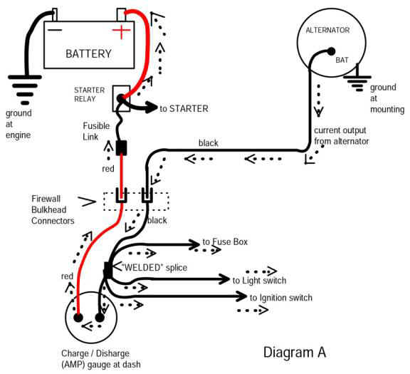
The important diagram from the above page:
This diagram illustrates how many many Mopars work for years and years. Even a 77 B200 van I junked out is set up this way. The main problems are, that the HIGH CURRENT charging and battery feeds go through the bulkhead on connectors which were never over sized, and have deteriorated with age. Additionally, in my lifetime, I've seen 4 cars in which the "in harness splice" failed (marked "welded splice" on the diagram)
Additionally, the ammeter and it's connections ITSELF can give problems, and then you have the "usual suspects" --worn out ignition switch, poor contacts in the connector for it, same for the headlight/ dimmer switch, and, the bulkhead connections feeding back OUT
The basic MAD bypass does the following: You run a charging jumper from the alternator to the starter relay, and then hook the ammeter wires together. This RELIEVES the heavy charging current from the harness into the interior, and NOW the TWO wires that used to operate the ammeter are now in PARALLEL, acting as one large wire to feed power INTO the interior of the car. The big wire jumper you install from the alternator to the starter relay effectively ties these two (the red and black) together into one large wire.
67Dart273:
I spent the afternoon surfing automotive wiring methods, and found MADs site as well as the diagram illustrating parallel conductors passing through bulkhead connector a continuous conductors, and amp gage removed from circuit.
I have two concerns with this method: one, parallel conductors without proper over current protection is not acceptable; two, removing the capability of disconnecting engine compartment harness from under dash harness is cumbersome if repairs to either require disconnection by running from engine compartment to factory splice continuous conductor . The instructions direct that an additional length of red & black conductor be included to facilitate repairs at the bulkhead connector.
I think if one were to undertake removing amp gage, and modifying power distribution and charging circuits as described in the MAD article, one #10 or # 8 passing through fire wall via a more electrical correct and user friendly method should be employed using a connector such as this Firewall Stud Insulator.
I must say their remote voltage sensing method of connecting voltage regulator to a common power distribution point with little or no voltage drop warrants additional consideration. Eliminating five or six points of voltage drops in our Chrysler voltage regulator circuit as current passes in and out of bulkhead connector would be helpful in maintaining proper voltage levels.
I need to think these harness redesigns over a little more before deciding what to do if anything.
daredevil
Well-Known Member
Dont see why not. Wrong sorry for the bad info. Sometimes I should keep my mouth shut.
67Dart273
Well-Known Member
Could I just tie both of my ammeter wires onto the positive post of my volt meter?
No, the voltmeter should have one terminal GROUNDED and the "hot" lead connected to "switched" ignition. On Mopars that terminal is a dedicated terminal on the ign switch, and as I said earlier, powers the ignition, regulator, etc,
but....it ALSO goes to the instrument cluster and powers the gauges through the voltage limiter
You should be able to splice into that. Bear in mind that originally, that circuit IS NOT FUSED.
67Dart273
Well-Known Member
I have two concerns with this method: one, parallel conductors without proper over current protection is not acceptable.
I do not disagree, although mine is currently (no pun!!) unprotected. If done as they suggest, the original fuse link still protects one of the conductors. If you bypass the alternator to the starter relay, it would be a simple matter to also put a second fuse link at the connection of the start relay stud and the bypass wire.
two, removing the capability of disconnecting engine compartment harness from under dash harness is cumbersome if repairs to either require disconnection by running from engine compartment to factory splice continuous conductor .
I know there are some that seem to believe you can repair these connectors "as is" but I've seen enough of 'em melted and damaged, and giving problems over the years that I'm just tired of the root of the problem. If you run an auxiliary relay box, to provide power for headlights, ignition, etc mounted underhood, this sort of eliminates the problem, because you can then disconnect the harness, pop the connector out of it's mount, and just snake what's left "into" the hole.
For what LITTLE (maybe never) that I'll ever need to "deharness" the car, this for me is a VERY minor point, compared to having a RELIABLE electrical system, with no real problems.
a more electrical correct and user friendly method should be employed using a connector such as this Firewall Stud Insulator. .
That or something along those lines is certainly an option. Let's not forget that on some of the earlier cars, the ammeter circuit (2 wires) were fed through SEPARATELY anyhow.
I must say their remote voltage sensing method of connecting voltage regulator to a common power distribution point with little or no voltage drop warrants additional consideration. Eliminating five or six points of voltage drops in our Chrysler voltage regulator circuit as current passes in and out of bulkhead connector would be helpful in maintaining proper voltage levels..
That is absolutely a concern, and the biggest one is the switched ignition circuit. Not only does the voltage drop cause overcharging while running, but can cause starting problems because without the alternator running, that voltage is LOW just when the key is released, the engine may be stumbling trying to run, and the charging system is not yet putting out.
The positive connection to a volt meter would be a dark blue with white tracer. It comes away from the ignition switch and goes to the instrument panel in all models.
What you do with the original amp gauge wires and the rest of the electrical is your decision.
What you do with the original amp gauge wires and the rest of the electrical is your decision.
daredevil
Well-Known Member
No, the voltmeter should have one terminal GROUNDED and the "hot" lead connected to "switched" ignition. On Mopars that terminal is a dedicated terminal on the ign switch, and as I said earlier, powers the ignition, regulator, etc,
but....it ALSO goes to the instrument cluster and powers the gauges through the voltage limiter
You should be able to splice into that. Bear in mind that originally, that circuit IS NOT FUSED.
So is this what kills my battery when my car sits for a week or two?I already know the answer.
67Dart273
Well-Known Member
So is this what kills my battery when my car sits for a week or two?I already know the answer.
I would guess it's a good start.....check with a test light in series with the ground lead to the battery, then unhook the voltmeter and see..................
This is a mock-up of how I do it. I use a Perma-seal step down splice, cut the dark blue/white tracer power wire like Redfish says and install the splice with a short lead to the voltmeter pos. terminal. connect the meter ground lead to any of the circuit board retainer screws and it's done.
View attachment DSCN1836 (Small).JPG
View attachment DSCN1836 (Small).JPG
green1
Well-Known Member
See madelctric figure B. do that, with the large new wire still outside the firewall. Go to the local alternator guy, and buy the fusible links, for $5. Just using a piece of smaller wire is NOT a fusible link, they are different beast.
Rewiring the headlights with short 10 gauge wires and high quality connectors, relay controlled from the OEM switch in the interior is also a smart move.
Look up Daniel Stern lighting, I understand he's a fellow Mopar nut of the slant six persuasion.
Look up Daniel Stern lighting, I understand he's a fellow Mopar nut of the slant six persuasion.
I did dive into my wiring harness and do several changes at once. For many owners it will likely be better to do one thing at a time. Stay on the amp meter to volt meter until complete. If you do anything, do it right. The volt meter should get a decent input signal from that dark blue w/ white. Voltage drop in the ignition switch , etc.. is possible but lets not go there yet.
Attaching the ground side of the volt meter to just anywhere on the instrument cluster is not efficient. Buy some wire and route that ground signal to a true chssis ground. A sheet metal screw with toothed washer behind the left kick panel is one option but
all the way to the battery ground terminal would be the very best. A 10 amp fuse in that wire is a good idea also since the only fuse in the positive side is the fusible link. You dont want a failed aftermarket gauge or chaffed wire to kill the whole car.
My inline fuses are behind the column cover and labelled so I know whats what. The volt meter inline fuse is in the blue w/ white. This explains why I ask others to sell pieces of wiring harnesses to me.
-


