Most of the vacuum lines on my 318 are 41+ years old so it crossed my mind that they should be replaced. I then looked closer at how many yards of line I’d have to replace and it was adding up so I thought getting rid of the vacuum lines would be a good idea. Best way to do that would be to get a pre-emissions manifold so my project/search began to upgrade my 2 barrel to a 4 barrel; I couldn’t go too wild since my car has collector plates and the insurance company is quite strict as to what modifications can be done to it without voiding my policy. I was considering a Weiand Stealth or a LD4B but settled on the LD4B since it is era correct and could be ordered through Chrysler which means it won’t void my insurance. After acquiring a LD4B the next step was choosing a carb and I settled on a 1406.
Depending on how quickly you want to do the project (and how much you want to spend) almost all of the parts are available new with the exception of the 4 barrel kick down rod that goes between the throttle bracket and carb. Year One sells an entire 4 barrel kick-down linkage down to the transmission but it’s several hundred $$ and 2/3’s of the components are not needed if you have the linkages already on your 904. I wasn’t in a rush so acquired the parts over several months.
I bounced some ideas/questions off a few members on the board here (thanks!) and some of you might recognize some of the parts. I know there are already a few threads on fabo about upgrading a 2 barrel to a 4 barrel which were helpful when sourcing the various parts required and this thread can add to the collection.
Now that the project is done, for those interested in doing the same thing, below is the complete parts list I used with equivalent part numbers
-Edelbrock LD4B intake manifold
-Edelbrock 1406 carb
-340 Six Pack coil mounting bracket (#407)
-Coil mounting bracket/ring (#8213)
-Throttle return spring, small block (#TS02)
-Throttle spring bracket, ’71 – ‘73 340 4 barrel (#736)
-Throttle cable bracket, ’68 - ’74 340/360 (#0060)
-Throttle kick-down spring, ’70-’74 (BF341)
-4 barrel kick-down rod (between carb and throttle bracket)
-Edelbrock carb linkage adaptor (1843)
-Fuel line flare fitting (AF440) only needed if you’re running a steel line to your carb instead of the suggested rubber line
-Edelbrock heat insulator gasket (9266)
-Fel-Pro intake manifold gasket (1243)
-Mopar performance valve cover gasket (MOPP5249581AB)
Tool:
-3/8” drive 9/16” torque adaptor (Proto 5118) Not required but is a must if you want to ensure the proper torque for several of the intake manifold bolts. It also prevented me from removing the distributor as I used it to remove/install the intake manifold bolt closest to the firewall that also holds the throttle cable bracket.
Here is what I was starting with:

A few vacuum lines:

Old intake manifold removed:

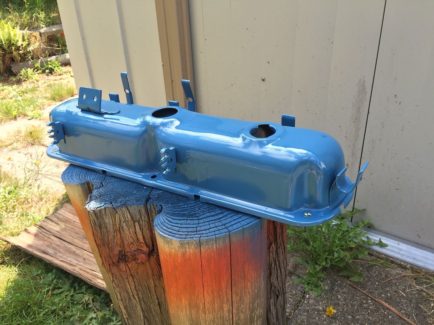
Valve covers and air cleaner could use some TLC so a little paint stripper and sanding/sand blasting resulted in something decent:


Other parts ready for paint:

4 barrel kickdownrod:

Did some test fitting and ready to place the intake on. When test fitting the LD4B with the Fel-pro gaskets, the manifold bolts wouldn’t line up with the threads in the head since the gasket was too thick. Solution to that was sanding down the head side of the gaskets so the intake would site lower and allow the bolts to line up with the threads in the head.

Since the LD4B does have coil mounting bosses, I used the 340-6 coil mounting bracket. The bracket required some grinding/cutting to clear the plenum it mounts around. As you can see in the photo, in 1975 there was a large wiring connector above the valve cover which made it difficult to mount the coil; thankfully the studs on the bracket are long so I used some washers to raise the coil mounting bracket/ring for more clearance when the coil was in place.

Although the 4 barrel small blocks have the fuel filter up top and visible, I prefer the cleaner look of the filter being tucked away under the alternator. Plus with fuel cleanliness being a lot better now compared to 40+ years ago, needing to check the filter every time the hood is open isn’t as important. I’m not sure why Edelbrock suggests using a rubber line to the carb so I replaced that fitting with a flare fitting for the 5/16” steel hose that I then bent down to the fuel filter below the alternator.


For the electric choke, in 1975 (perhaps the ’73 and ‘74’s have it too??) it had a single stage electric choke already so I reused the lead/connector that was already in the wiring loom. I double checked that it only provided power when in the “On” position which was the case. This saved time in having to run a wire off the 1406 elsewhere since it should not be connected to the coil.
Since there are always questions on the kickdown rod, here are a couple of photos:


Finished product:

I also replaced the distributor cap, spark plugs and plug wires since I had some time while I waited for some parts to arrive.
Aside from a fuel leak where the fuel line enters carb, which required re-flaring the line fitting, it fired up and ran. I’ve burped the coolant system and now need to play with the idle speed, mixture screws and timing.
Depending on how quickly you want to do the project (and how much you want to spend) almost all of the parts are available new with the exception of the 4 barrel kick down rod that goes between the throttle bracket and carb. Year One sells an entire 4 barrel kick-down linkage down to the transmission but it’s several hundred $$ and 2/3’s of the components are not needed if you have the linkages already on your 904. I wasn’t in a rush so acquired the parts over several months.
I bounced some ideas/questions off a few members on the board here (thanks!) and some of you might recognize some of the parts. I know there are already a few threads on fabo about upgrading a 2 barrel to a 4 barrel which were helpful when sourcing the various parts required and this thread can add to the collection.
Now that the project is done, for those interested in doing the same thing, below is the complete parts list I used with equivalent part numbers
-Edelbrock LD4B intake manifold
-Edelbrock 1406 carb
-340 Six Pack coil mounting bracket (#407)
-Coil mounting bracket/ring (#8213)
-Throttle return spring, small block (#TS02)
-Throttle spring bracket, ’71 – ‘73 340 4 barrel (#736)
-Throttle cable bracket, ’68 - ’74 340/360 (#0060)
-Throttle kick-down spring, ’70-’74 (BF341)
-4 barrel kick-down rod (between carb and throttle bracket)
-Edelbrock carb linkage adaptor (1843)
-Fuel line flare fitting (AF440) only needed if you’re running a steel line to your carb instead of the suggested rubber line
-Edelbrock heat insulator gasket (9266)
-Fel-Pro intake manifold gasket (1243)
-Mopar performance valve cover gasket (MOPP5249581AB)
Tool:
-3/8” drive 9/16” torque adaptor (Proto 5118) Not required but is a must if you want to ensure the proper torque for several of the intake manifold bolts. It also prevented me from removing the distributor as I used it to remove/install the intake manifold bolt closest to the firewall that also holds the throttle cable bracket.
Here is what I was starting with:
A few vacuum lines:
Old intake manifold removed:
Valve covers and air cleaner could use some TLC so a little paint stripper and sanding/sand blasting resulted in something decent:
Other parts ready for paint:
4 barrel kickdownrod:
Did some test fitting and ready to place the intake on. When test fitting the LD4B with the Fel-pro gaskets, the manifold bolts wouldn’t line up with the threads in the head since the gasket was too thick. Solution to that was sanding down the head side of the gaskets so the intake would site lower and allow the bolts to line up with the threads in the head.
Since the LD4B does have coil mounting bosses, I used the 340-6 coil mounting bracket. The bracket required some grinding/cutting to clear the plenum it mounts around. As you can see in the photo, in 1975 there was a large wiring connector above the valve cover which made it difficult to mount the coil; thankfully the studs on the bracket are long so I used some washers to raise the coil mounting bracket/ring for more clearance when the coil was in place.
Although the 4 barrel small blocks have the fuel filter up top and visible, I prefer the cleaner look of the filter being tucked away under the alternator. Plus with fuel cleanliness being a lot better now compared to 40+ years ago, needing to check the filter every time the hood is open isn’t as important. I’m not sure why Edelbrock suggests using a rubber line to the carb so I replaced that fitting with a flare fitting for the 5/16” steel hose that I then bent down to the fuel filter below the alternator.
For the electric choke, in 1975 (perhaps the ’73 and ‘74’s have it too??) it had a single stage electric choke already so I reused the lead/connector that was already in the wiring loom. I double checked that it only provided power when in the “On” position which was the case. This saved time in having to run a wire off the 1406 elsewhere since it should not be connected to the coil.
Since there are always questions on the kickdown rod, here are a couple of photos:
Finished product:
I also replaced the distributor cap, spark plugs and plug wires since I had some time while I waited for some parts to arrive.
Aside from a fuel leak where the fuel line enters carb, which required re-flaring the line fitting, it fired up and ran. I’ve burped the coolant system and now need to play with the idle speed, mixture screws and timing.
")