Printed circuit pins repair

-

Pompis

Well-Known Member
Joined
Nov 16, 2012
Messages
229
Reaction score
22
Location
Sweden
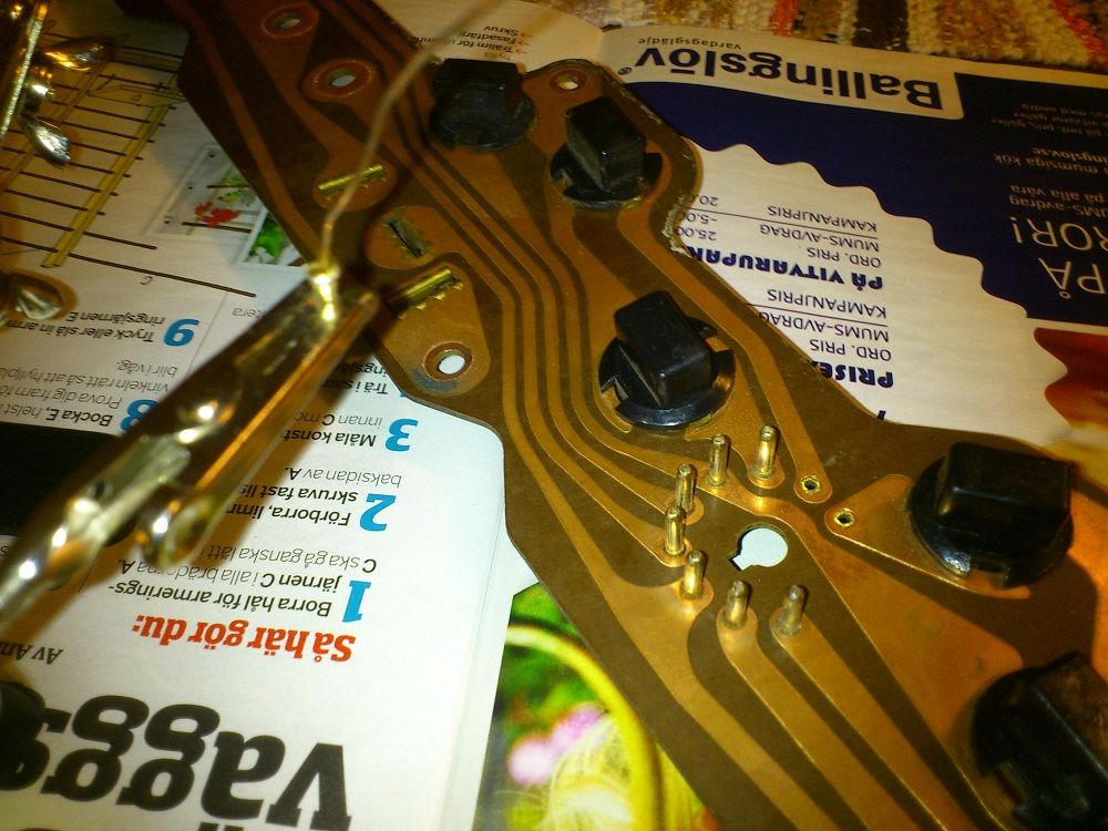
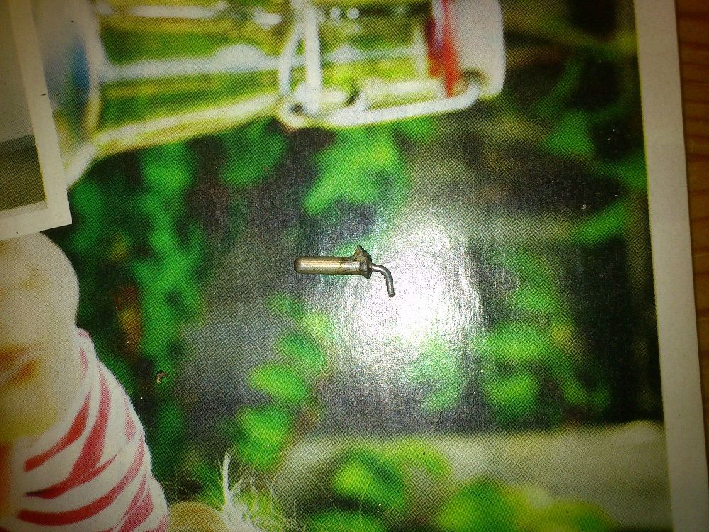
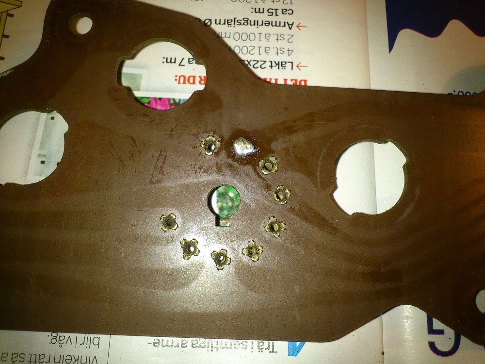
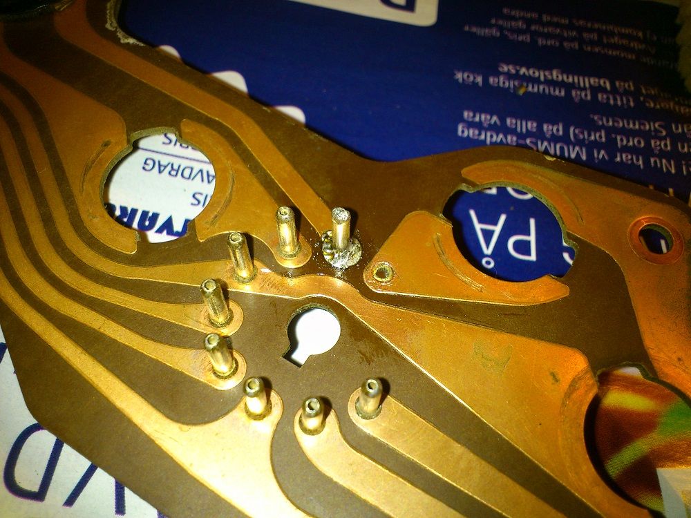
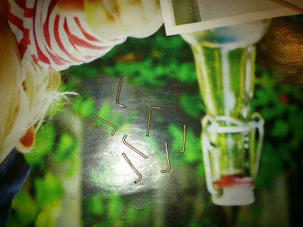
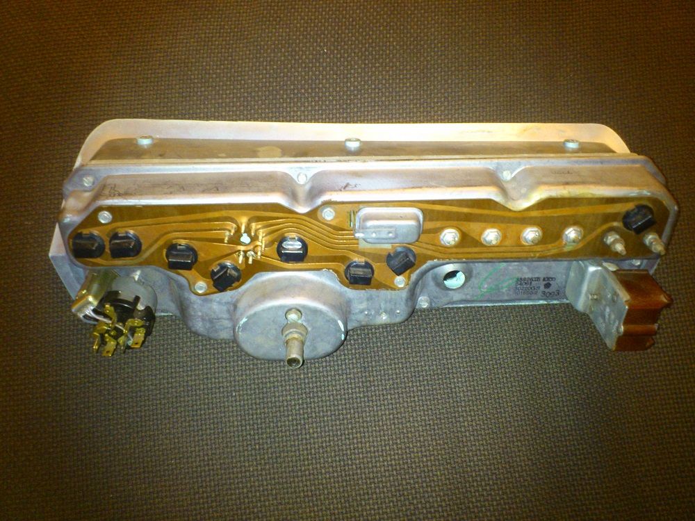
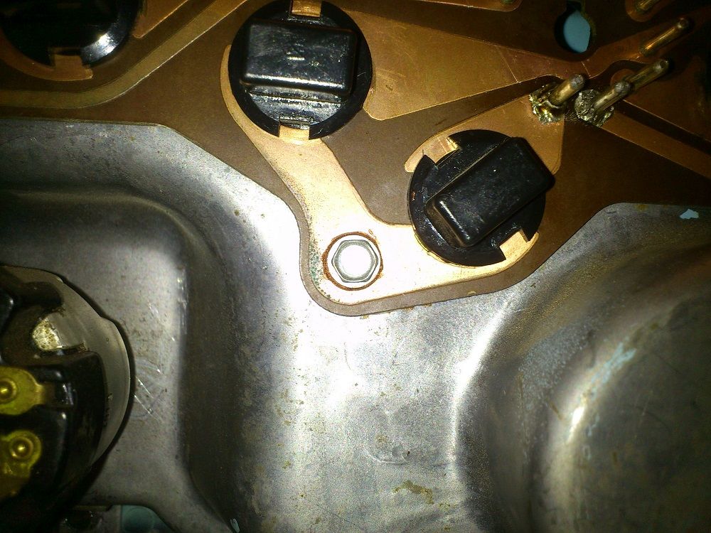
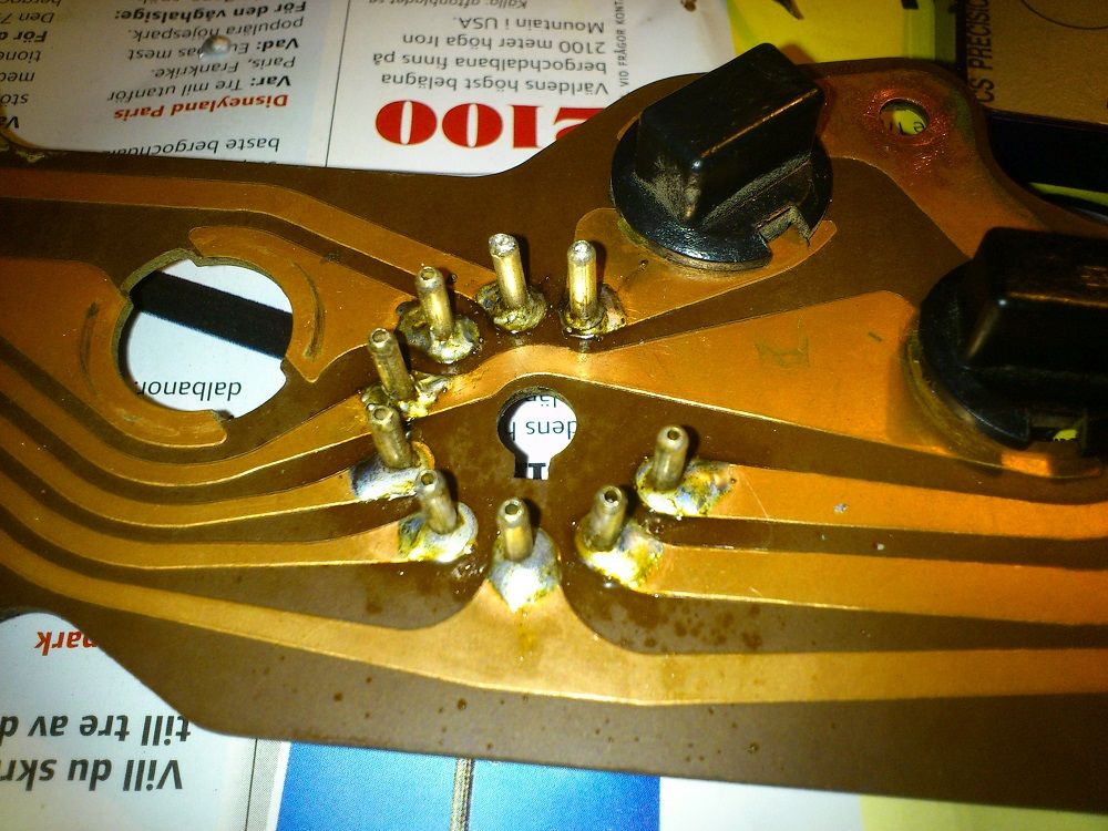
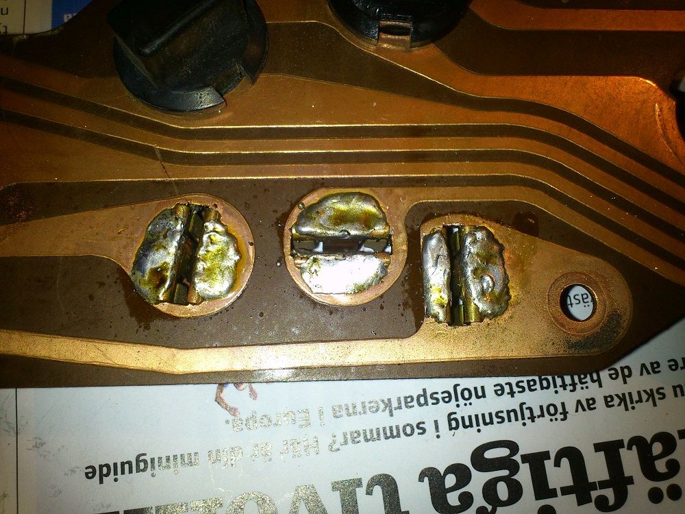
Today when I removed the dashboard I managed to break of two pins. :eek:ops:

DSC_1428_zpsa3bc295e.jpg


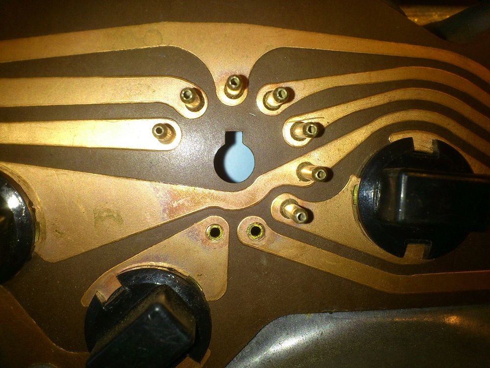
And I wonder if it can be repaired? If so have anyone of you any ideas?
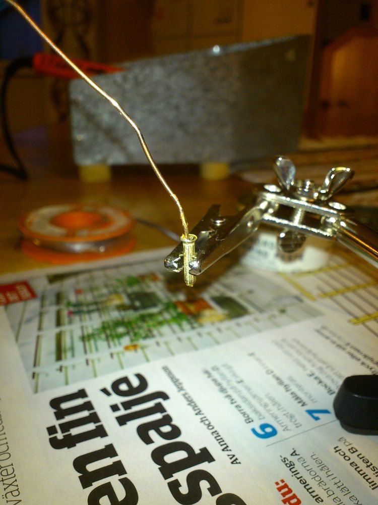
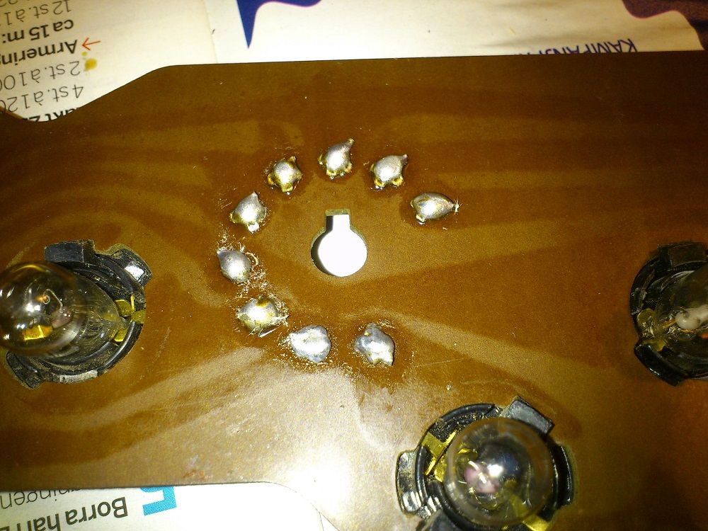
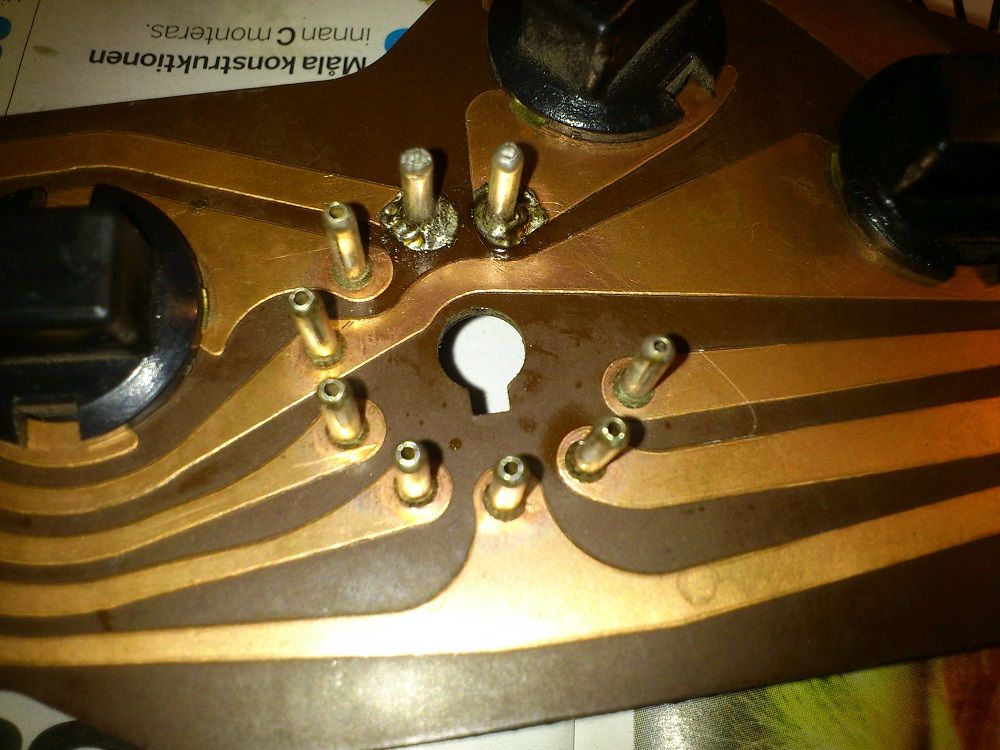
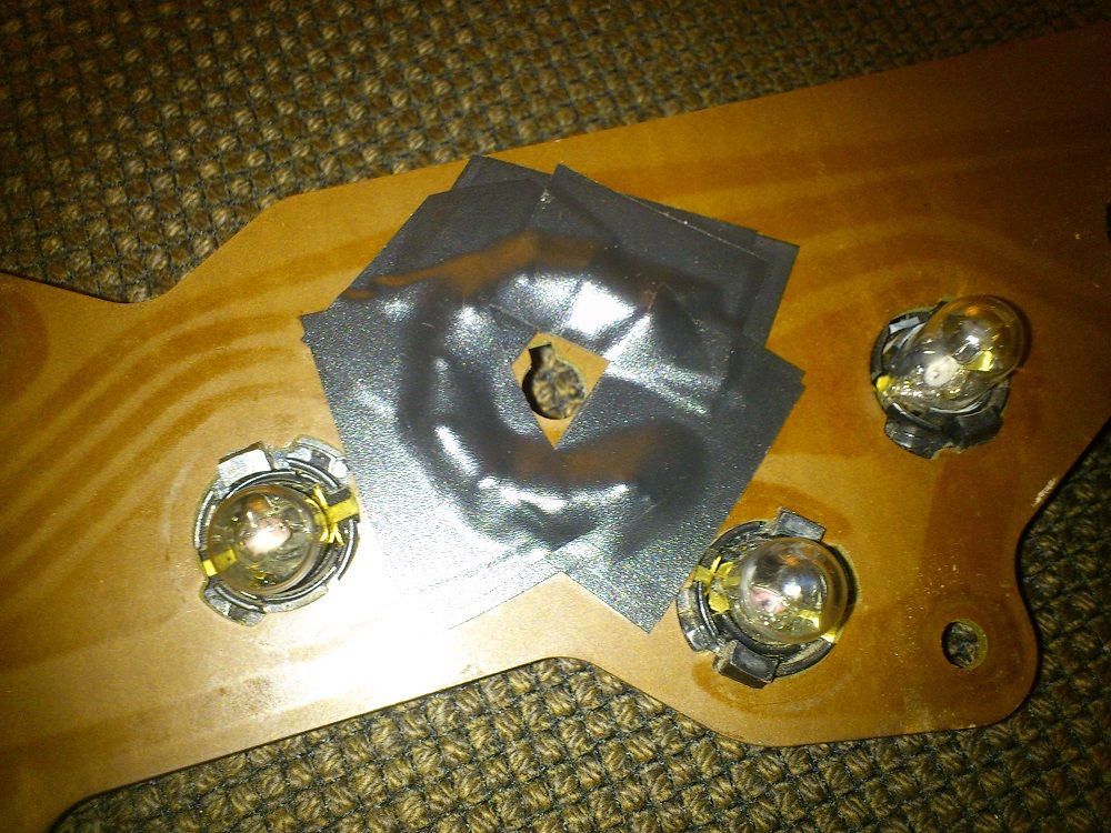
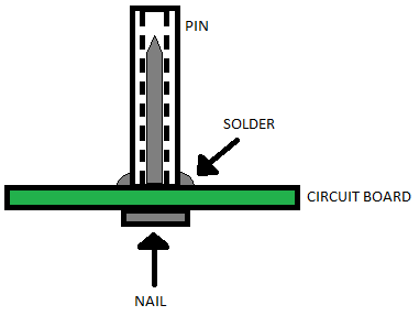
Would greatly appreciate some input how to repair them. Have one idea to solder the pins back and secure them like this.

Circuitboard_zpseea80ab4.png
 
use the diagram you have to repair. make sure the nail head is thin. I just use solder w/o nail but I do that with loose ones.
 
Guys have done this. Go to your hardware store and look for brass brads.

Mine had "most of" the pins broken or loose, so I didn't even repair them. I simply scrapped the copper clean, soldered lead wires to each, and ran a ft or so of wire off to Molex style connectors.
 
Mine had "most of" the pins broken or loose, so I didn't even repair them. I simply scrapped the copper clean, soldered lead wires to each, and ran a ft or so of wire off to Molex style connectors.[/QUOTE]

X2! I used a soldering iron, not a gun or it will get to hot. And defiantly use rosin type FLUX!!!! or it won't stick. Rosin core solder is good but a little extra flux can really help clean the area to be soldered. Get a little bit of solder on the tip of the iron when the iron is hot, before you go at the printed circuit. This will help transfer heat faster and finish the joint faster so you won't melt the p.c. Never acid core solder or acid flux on electrical. That's for the plumbers. IMO
Larry
 
CLEAN them best you can. Fortunately, copper is soft and easy to clean

BUY some solder that is specified for electrical / radio / TV work. Radio Shack solder isn't that bad

Also you might go to your local welding store and see if they have a product called "No Corrode". Not sure of the spelling I was unable to Google it. It is a pink past flux, used to be in a tin can. Make CERTAIN if you but a separate flux, it s safe for electrical, and not acidic
 
Thanks for the tips. Made it as player1up did, sort of. Cleaned it up and used flux to get the paperclip to stick. Became very strong and I reinforced the all the other pins so they not come loose because some of them you could wiggle around. Made all of them with a "barb" so they can't pull out as easy. Not the prettiest soldering but I'm very happy with the outcome and I hope someone else could use this information too.

DSC_1429_zpsdec44e50.jpg


DSC_1430_zps7d5c4506.jpg


DSC_1434_zps7cfddf02.jpg


DSC_1432_zpsa2ca2829.jpg


DSC_1433_zps8c97fbf5.jpg


DSC_1435_zpsf2e650ac.jpg


DSC_1436_zpsf9dd51ab.jpg


DSC_1437_zps58cdaf12.jpg


DSC_1439_zps26baec19.jpg
 
There isn't a lot of clearance cut into the housing. If the leg of the L touches metal...
I'm not saying is see a problem. It's what I cant see that concerns me.
Good luck with it.
 
I have to tell you that your soldering does not look that good. You need to get some small tools, even a sharp small screwdriver blade if nothing else, knife, abrasive, pencil eraser, whatever you can come up with that is CLEAN and get the surface oxidation off the board

That joint appears to be what is called a "cold" joint. you DO have to be careful not to overheat the board, as you can separate the foil from the board, but it appears that for that joint you need more heat to "flow" the solder

Also refer to your other thread, where I was referring to repair of the gauge limiter socket. See how those contact fingers are crimped into the board? They may NOT be actually making good contact with the board.
 

Attachments

  • joint.jpg
    21.5 KB · Views: 967
  • scrape.jpg
    11.2 KB · Views: 899
Thanks RedFish for that information. Took it apart again to check the clearance and I became worried so I electric taped over the L end at the backside to protect from grounding. Put some copper grease on the screws that connect with the circuit board for better connection too. Now I think it's done properly.

DSC_1420_zpsd34f2bd6.jpg


DSC_1421_zps969110cb.jpg


DSC_1423_zps705a4104.jpg
 
Do you have a meter? Check continuity from the pin to the surface where the bulb sockets contact. Easier than puting it back in to find your turn sinal indicators don't work.
 
I also solder lead wires to each, and ran a ft or so of wire off to Molex style connectors.
 
I've done that exact repair several times. Those boards are pretty well made compared to some that I have worked on (nothing pulls traces up like the circuit boards that All American Scoreboards uses).
 
Third time's the charm:) Now I have soldered all the pins after checking with the meter and I had two pins that had bad connection. Everything works properly now. Soldered the gauge limiter socket also after your input 67Dart273. The joint was not a cold joint, it was just me that did a ugly joint but I fixed it now. Thanks again for yours help

DSC_1420_zps45673b88.jpg


DSC_1421_zpsa3d00147.jpg
 
!!very good!!
 

Attachments

  • review-very-good.gif
    11.4 KB · Views: 850
Good work. Most of the soldering looks correct, with the solder in smooth volcanoes that flows up on the pins. Wash off the flux well. I use GoJo or Lava soap on a toothbrush. At a past company, they washed new circuit boards in a dishwasher to remove flux, so don't be afraid of water. These repairs are easy, and anyone can do them. You should see how people repair modern circuit boards with tiny traces. Possible, but takes much skill and proper equipment.
 
Third time's the charm:) Now I have soldered all the pins after checking with the meter and I had two pins that had bad connection. Everything works properly now. Soldered the gauge limiter socket also after your input 67Dart273. The joint was not a cold joint, it was just me that did a ugly joint but I fixed it now. Thanks again for yours help

Photobucket nag screen chumps!
Untitled.png
 
Last edited:
-
Back
Top