starter relay wiring

-

oneownr67

Member
Joined
Nov 21, 2014
Messages
16
Reaction score
5
Location
Illinois
I am putting stuff back on the 67 coupe. I can't figure out the wiring for starter relay on the left fender. I think the big post has a wire from the battery and one to the starter. I found a slip-on connection that fits the spade that is at an angle. That leaves a small screw down connection. I can't figure out a wire for it. I am not sure the connections to the big post are correct.


I can't find any photos and the wiring diagrams show 4 connectors.


Any help will be greatly appreciated


Thanks

Omar
 
The square screw connector is a large gauge single wire that only goes on place........from the relay down to the small terminal on the starter. this is normally about no12 or so wire
 
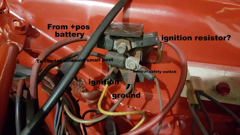
For original type wiring: The large lug on the starter gets a wire from the battery (the smaller of the 2 wires from the battery; the big wire from the battery goes direct to the starter), plus the fusible link wire to the firewall connector.

The screw down connection goes to the solenoid lug on the starter, which is the smaller of the 2 starter lugs. This wire is a medium sized brown wire.

The wire to the angled connection should be yellow and come from the firewall connector.

If this is a manual trans car, that is all for a '67. If an auto, there should be a smaller brown wire to a 4th spade-type connection; that small brown wire goes to the Neutral Safety Switch (NSS) on the trans.
 
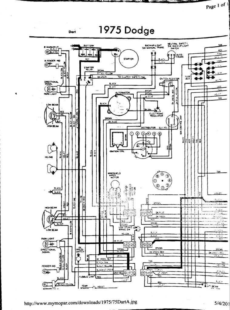
Just went through some stuff with my start and thanks to 67Dart I got it figured. Also I know the wiring on the relay pretty good now too. Heres a picture of my /6 starter relay with labels as well as some diagrams too. Not sure how much different it is then the 67 though. correct me if i'm wrong guys.


Be aware that the manual trans clutch safety switch was not added 'til later. So some earlier manual trans cars had no 4th connection on the starter relay. And very early auto trans cars did not either. So a '75 schematic used for a '67 may mislead you in this.
 
So are the traces in color of the original 67 drawings wrong?

If so some constructive feedback would be welcome to revise them.

If you go to mymopar and look at the 69 Barracuda color set guess where they came from! I am glad they saw fit to post them there.

I do not have a copy of the original accessory wiring docs for 67 as they are not included in the main service manual and were released seperatley unlike 68 and later.

Wrong in the factory manual? I don't think so..........

The colors ARE in the factory manual, they are simply "done differently."

67 manual

http://www.mymopar.com/downloads/servicemanuals/1967_Dart_Coronet_Charger_Service_Manual.zip

Here's a sample mayb? what you are referring to?

You have to take the wire number (circuit number) and look at the chart on the side of the page, which then gives you the color.

Example you can see one of the lamps is wire "E2A." If you find E2A on the chart it is ORANGE a common color for dash lighting
 

Attachments

  • colors.jpg
    121.1 KB · Views: 542
The problem with all the drawings posted is that they are not correct. You can download the FACTORY service manual for free, some here

Guess I was refering to is this statement.

The drawings I post are traces of the originals factory diagrams with the possible human errors in the trace. They are recreated in color and without the cross reference of the pre 68 diagrams. I belive they are easier to follow and in some cases split sheets are now combined on one page. Yes the factory drawings in some cases are wrong as well. Look at the 69 HEMI engine compartment drawing from the Plymouth service manual. The connections on the starter relay is wrong. The power feed through the bulkhead is shown connecting to the starter solenoid post.

So like asked good feedback helps everyone when good accurate drawings are available.
 
Sorry I was referring specifically to the aftermarket ones which are the same origin as MyMopar. I don't know where those originated. They are not factory. They ARE in many cases useful. The point I was trying to make is that they leave out some options and more importantly (esp later models) certain connectors, which can throw someone "for a loop."

Those color ones are actually pretty good
 
-
Back
Top