Alternator voltage regulator teardown and analysis

-

MadScientistMat

Well-Known Member
Joined
Mar 6, 2008
Messages
605
Reaction score
207
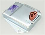
We've had a few discussions of the current state of replacement voltage regulators for our Mopars, such as this thread. To get a closer look at what's going on in your general parts-store replacement Chrysler alternator voltage regulator, I have bought one (a MasterPro 2VR1, about $32 at O'Reilly), and will take it apart and put it under a microscope to show you how it works and where these may have room for improvement.

From the outside, it looks like your standard voltage regulator. We have a stamped sheet metal casing and a molded plastic connector with a folded metal bracket.

IMG_20230729_141734980.jpg

The back is sealed with potting compound. There are several types of material that can be called potting compound; they are usually epoxies or urethane.
IMG_20230729_141833630.jpg

As this material cuts easily with a knife, I'm going to say it is most likely urethane. I switched to a box cutter after this picture was taken. I could have used something more aggressive, but didn't know if there was anything inside the potting compound that might be damaged.

IMG_20230801_193738341.jpg

Enough cutting revealed a layer of sand under the potting compound.

IMG_20230801_194937986.jpg

Once I had cut around the perimeter of the potting compound, I was able to pry it out to see what was under it.
IMG_20230801_195227379.jpg

The potting compound peeled off in one piece.
IMG_20230801_195234069.jpg

Here's what's underneath. The wire on the right was caught in the potting compound and broke off the circuit board. Let's have a look under that sand..
IMG_20230801_195742362.jpg

Here we have a surface mount, single sided PCB. Probably FR2 or a similar laminated paper substrate. There are a total of 12 components populating the board, nothing more complex than a transistor.
IMG_20230802_183147977.jpg

When I said I would put this under a microscope, I meant it. Stay tuned for an analysis of the circuit board.
 
For the workings of the isolated field regulators, the end of this thread is a good starting point.

Feel free to build onto the rough schematic.
@KitCarlson identified a number of the components in the Chrysler illustrations
 
Last edited:
I will follow this. Why don't they make these adjustable? Would be simple to do.
 
I will follow this. Why don't they make these adjustable? Would be simple to do.
Adjustable VRs are over-rated. IF the wiring and grounds are sound, IF the battery is in good condition, and IF the VR is working correctly, there is absolutely no reason to adjust voltage. IF any of the problems exist, they should be repaired rather than twisting a screw
 
I am only saying- I believe there is a certain inconsistency in the components or manufacturing process that could be fine tuned. Always appreciate your input.
 
I am only saying- I believe there is a certain inconsistency in the components or manufacturing process that could be fine tuned. Always appreciate your input.
Actually someone aftermarket DOES make them. And you could "used to " buy the heavy duty one from 69/ earlier.

Here's one for 70/ later


This was the old one, also sold by Standard / Blue Streak. We used to stock them

VRadjustable.jpg
 
My copy of KiCad is being stubborn today, so we'll need to make due with a hand drawn schematic.

This is a very simple circuit, using a large power transistor and a smaller transistor to switch the larger one. The switching transistor is controlled by a Zener diode, Z1 on the circuit. When the voltage rises high enough, it flows through the zener diode and turns on the smaller transistor, which switches the large one off. When the voltage is low enough, current through Z1 shuts off, the large transistor switches on, and grounds the field coil. There is a capcitive coupling between the output of the power transistor and the switching transistor that limits the maximum switching speed. The reason for this is that switching off the power transistor creates a large voltage spike, which the D1 diode dumps back into the supply voltage. If the switching is too rapid, this will send too much current through D1 and can burn out D1, or even the 12 volt feed wire.

IMG_20230805_124348190.jpg


This is a rather simple circuit and rather similar to Chrysler's original design that Mattix posted in the other thread. One conspicuously absent feature is any sort of temperature compensation; batteries often need more charging voltage at lower temperatures.
 
The Chrysler version had a couple resistors if I recall correctly.
It was not clear to me if either were used to to provide reduced current to the rotor's windings.
That would make it more like the electro-mechanical regulator used with the grounded field alternators.
I can't recall if Chrysler provided a photo of the circuit board.
 
So far just the photo of the top.
Looks like two smaller solid state resistors and three wire wound not called out in the illustration?
And then cap as well is not called out.
1691258427162.png

No other photos of the internals else in that master tech booklet.
Rereading the booklet and Kit's description, it sounds like the supressor diode reduces spikes but the current regulation is on/off (unlike the earlier regulator with three positions; on, reduced current, off)
 
So, first, here's what they did well with this regulator.

The soldering work on the PCB itself is first-rate. I'm guessing it was run on an automated production line using solder paste and a reflow oven. It's not impossible to hand place components like this, but getting them placed that precisely isn't easy. And the solder joints are almost certainly not hand-soldered with an iron.

The circuit itself is a very simple design with not much to go wrong and not much that can kill it. The most likely things that could damage the circuit are water intrusion or an alternator field coil that draws more current than the power transistor can handle. Unfortunately, I could not find any markings on the power transistor, so I don't know what its maximum current is. Even though there aren't any discrete components for protecting it against voltage spikes, this circuit should be able to withstand spikes to 40 to 60 volts without any problem, possibly even higher.

And here are the areas of concern.

While the PCB soldering is done very well, the wire soldering is second-rate. While the joints look functional, their technician seems to subscribe to the idea of "The bigger the blob, the better the job." The conformal coating job was also done poorly, leaving many areas of the board uncovered.

I don't like the idea of a sand filled box. Sand filled electronics have valid applications where there's a concern about a box getting filled with explosive gas, such as natural gas pipeline stations, but that doesn't apply here. While this box didn't show any signs it would leak, if you made a mistake like leaving a big greasy fingerprint around the area where the urethane fills the box, it's game over. On the upside, it does make teardowns easier - perhaps their warranty department insisted on this. It's not an unacceptable way to build electronics, but I don't like it.

As noted before, there's no temperature compensation. It runs at a fixed voltage.

And then there's the issue of tolerances. The resistors are cheap 5% tolerance pieces. Zener diode voltage tolerances are also around 5% unless you spring for something special. Theoretically, you could stack the tolerances so the voltage is off by 15%. That is unlikely to happen in practice, but it is theoretically possible. Most of these are probably going to be within 5% of their target voltage. Murray's concern about tolerance stack-up was entirely justified here - the tolerances are very sloppy on this unit.

Heat sinking isn't ideal, but this circuit doesn't put out a lot of heat, either.

Last, areas where it could be improved.

Chrysler's original design used a thermistor to increase output voltage at low temperature.

An adjustable target voltage isn't necessary if the regulator is always at the voltage where it needs to be. Also, different batteries have different target voltages. 13.8 volts on a lead-acid battery may not charge quite as fast as higher voltage, but it reduces corrosion on terminals. However, a lithium-ion battery won't charge if the voltage is below the mid-14s.

Some other improvements wouldn't match factory Mopar wiring. For example, allowing the regulator to wire directly to the battery positive and ground would give a more accurate voltage reference, but you'd need a separate way to switch power so it doens't hold the alternator on. You could also add an alternator warning light output if it cannot hit its target voltage. Neither of those would work with a schematic at all like the one shown, but it's definitely possible.
 
I have to ask the question, is it really worth all your time and effort for an unknown, aftermarket, cheap china etc etc look alike replacement, that you already know does not conform to OEM.

I would much rather have an in depth write up on the OEM circuit, maybe even a heavier transistor so that field current could be dealt with.

I am not a designer. Once in awhile I manage to repair something, but generally speaking, I do not do well on undocumented equipment or components
 
Thanks for doing that.
Yes agree it would be good to have an original mopar one as the baseline.

I should clarify something. The transistorized regulators I've personally had fail are substitutes for the grounded field regulators.
These include the P-part regulators (which were recommended by DC when using Chrysler type electronic ignition with a grounded field alternator), and Standard Motor Parts VR-128 that Dan Stern often recommends, and similar. Currently I'm using FBO's that is in a housing that looks similar to the original electromechanical regulators. I have not broken that one, but also only used it for a short time with a revised squareback alternator.
 
LOL maybe it's time for an "external amplifier" that the VR can drive, and then drive the field
 
I have to ask the question, is it really worth all your time and effort for an unknown, aftermarket, cheap china etc etc look alike replacement, that you already know does not conform to OEM.
In this case, what prompted me to take a look at voltage regulators were reports that the quality on parts store replacement regulators had really gone downhill. So I started by looking at a representative example of what you'd find at a parts store to see just how bad they are. I also wanted to check if the design was based on Chrysler's original circuit or some sort of later technology, as for a while there have been monolithic alternator-voltage-regulator-on-a-chip devices and other developments. In this case, it looks like they've copied Chrysler's circuit with newer components, and copied it badly. They either did not notice that one of the resistors was a thermistor, or didn't care.

That said, I wouldn't mind taking a look at an OE Chrysler regulator for comparison, if anyone has a dead one for me to take a look at. Based on the picture that Mattix posed, I suspect the schematic for an OE Chrysler regulator is very similar as it contains the same components, except the thermistor, which the new part replaces with a resistor. I was able to identify the big and little transistors, suppressor diode, and zener diode on the circuit board in the regulator I looked at.

PM me or send me an email if you have a failed OE solid state regulator I can look at. The only one I have in my box of junk parts is a points type.
 
-
Back
Top