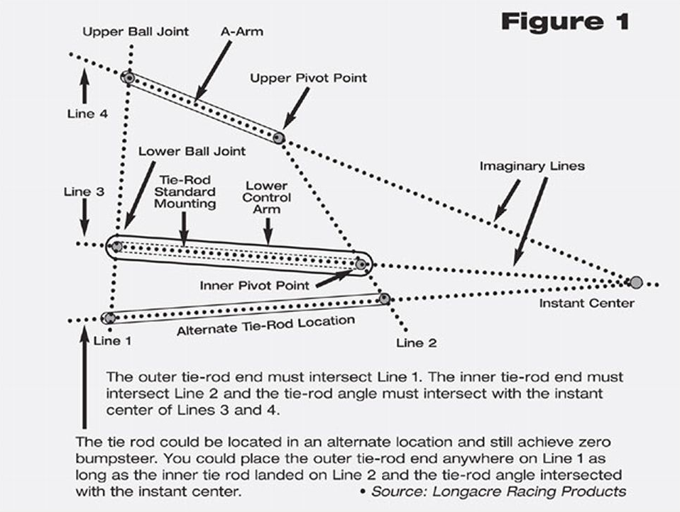
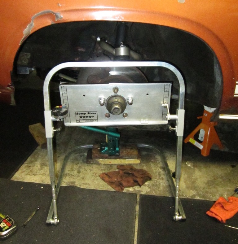
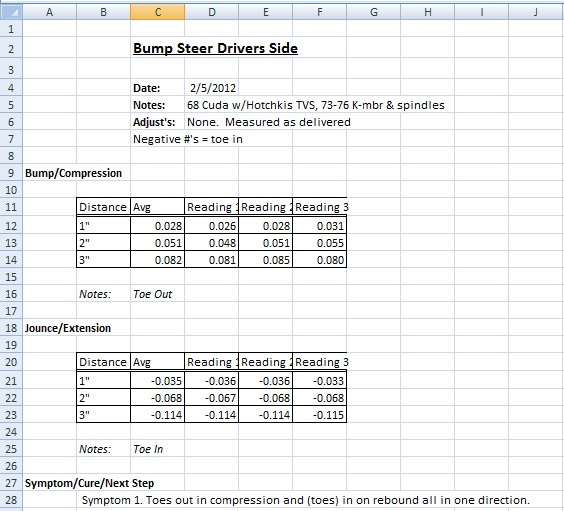
Having the tie rods level sounds very simplistic. A line drawn through the upper control arm, lower control arm, and tie rod end pivot points must intersect at the same point, and to do so, the tie rod can't be parallel to the lower control arm. Impossible to actually do on a vehicle, but the effect can be measured. One needs to measure toe change on a wheel as it is moved up and down. This is something I'm working on now getting our team's car ready for the next race. It's a Mustang. People buy bump steer kits for them, which adjust the tie rod height with shims. Following are instructions for a Mustang, but measuring on a Mopar would be the same, so reading that will give you a good understanding of what to do. I already have a dial indicator, so I'm just making my own fixture tool. I'm sure you could also tape a plum bob to the front and back of the tire, mark on the ground, raise the wheel an inch at a time, and check the difference. You'll have to measure the change on the ground in each plumb bob, and subtract those values from each other to see the change in toe since the wheel moves in and out as it moves up and down. It's the left and right movement that you need to measure. Make a reference of where the wheel is at ride height, take the tension off the torsions, and move the wheel through it's range of motion in one inch increments. There's always some bump steer, but you want as little as possible +1" and -1" from ride height. You want less than .020" toe change per side for every inch of wheel travel.
http://www.maximummotorsports.com/Assets/install/pdf/steering/MMTR-1-3-5-6r3.pdf
 and while that may be a correct observation, the cause could be incorrect geometry, could be bent / worn / loose anything in the system.


