EZ Wiring Mini 20 Circuit Installation

-
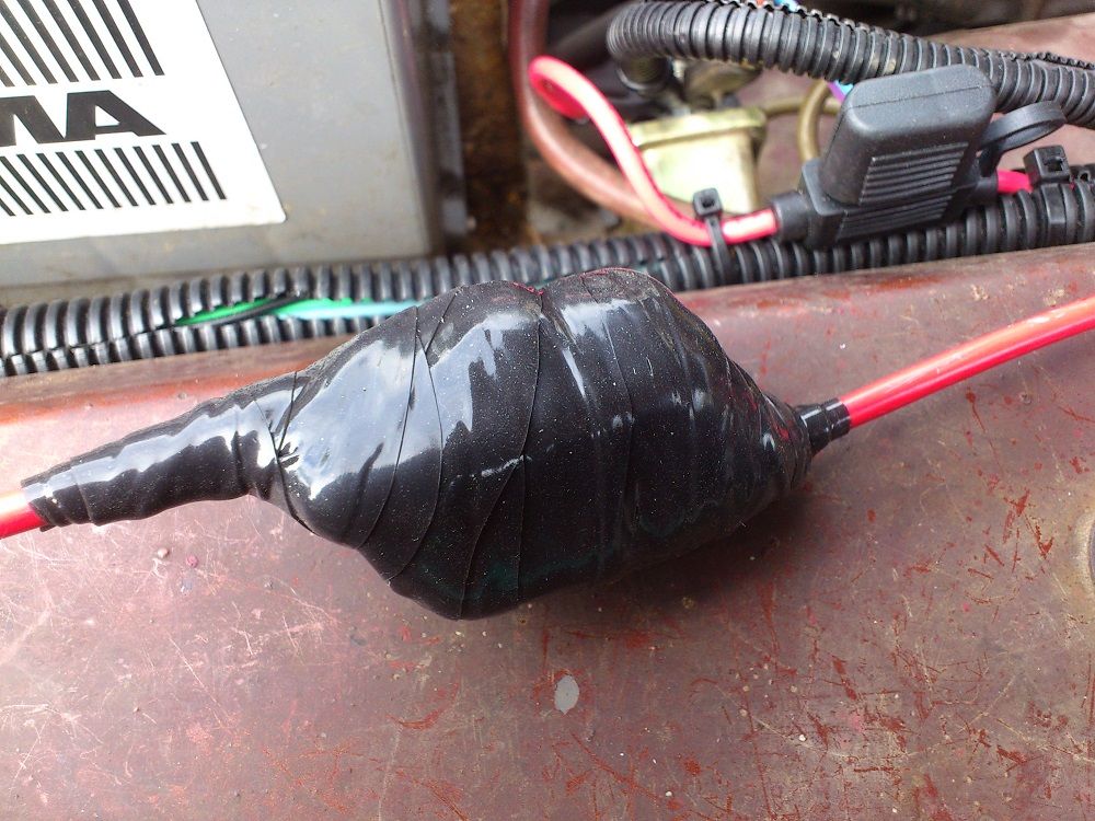
Thank you for the extremely detailed and helpful post. Too late for you now, but for others attempting such, I recommend looking at smooth PVC sheath, like from SPC Technology. You must pull the wires thru before terminating. I used it on my Dart & Valiant where I could. I used it long ago in an engineering design, and since saw they they used similar tubing extensively in my M-B 300D's. Much easier to keep clean than split loom.
 
Thanks Bill for yours advice I forgot that you recommended me that.

Now the car is done and everything seems to work except when I try start the car. The car starts in start position but stops when the key is released to run position. I have connected everything like the EZ manual shows but the EZ harness use the start feed from the start relay instead of the brown wire. I have tried different things but doesn't make it work.


This picture shows how you should connect the wires. EZ ignition switch conversion shows that the brown wire that's only have power when the key is in start position should connect to the Pink wire which is the Pink coil positive wire in the right diagram. That doesn't make sense since in start postion utilise the power from the start relay already. So when the key is released to run position it should have power on the Pink wire so I switched the brown and blue wire so it have power in run position but it doesn't work either. Some one have any suggestions?
DSC_1790_zpscf29add9.jpg


Thanks FABO
 
Sounds like the same mistake I made, and I was wiring my own harness to an underhood relay box (95 Jeep). I ASSumed that IGN1 (blu) got power when cranking ("start" position), so wired only IGN1. I wasn't using a ballast resistor. I found that only IGN2 (brown) gets power in "start", and vice-versa in "run". My engine wouldn't fire no matter how long I cranked, but as soon as I released the key to "run" it would fire. Took a while to figure that out. Simple solution, I just jumpered IGN1 & IGN2 at the key switch, by removing the factory terminal and making a jumper with piggy-back spade terminal. In my case, the IGN1/IGN2 wire just turns on an underhood relay that supplies my IGN bus (ignition, alternator, ...).
 
I did like you mentioned but it would not run anyway. I have also changed carb and intake and I was told that's important to change the old intake gasket which I didn't do. So I ordered a new intake gasket and hope that's cures the problem.
 
Ok, so what you need to do is this:


I connected their orange and brown wires together, then ran an extra wire (smaller red) from the factory brown wire on the ignition switch. This connects to the resistor where the original brown one would to work in the start position. The blue (pink in EZ-harness) connects to the other side of the resistor. I didn't jump from the relay to the start side like they do in the picture on that page.

In actuality, on my car, the red I added and the pink connect together since I eliminated the resistor completely.
 
Thanks goldduster for your explanation. Was thinking to do exactly as you described but now I know someone else tried it with success, so I will do it now.
 
Did the modification like above mentioned and the car started! :) Feels great that it runs because soon the new cam, lifters, spring, timing chain and gear arrive.
 
The IGN post they show on the starter relay is a separate contact used on the later Jeep style relays. If you are using your original type relay, it won't have that contact. This is what they are referring to:

starter_motor_relay1%20_199c.gif


The "whole deal" with resistor bypass on Mopars is right in the ignition switch.

Also, your fuel filter and that little pump "may" give you trouble. Most generic can filters do not work well on the suction side of the pump as they have too much restriction.
 
Thanks for the clarification and explanation on that
, didn't know that but it all makes sense now.

I know about the filter restriction but didn't when I mounted it, but it works so far.

But I have another problem that you 67Dart273 probably can help me with. The alternator charging to much. Have a new VR(cheap one), the battery is good and the voltage drop is 0.2V between Blue and postive post on battery and 0.15V between Blue and IGN on ballast. The ignition switch works good. Have good ground but still it outputs to much (16-18V) and the ammeter pointing heavily to discharge(left). Is it the alternator that is the culprit or is the VR bad?

EDIT:
I went out and did some more voltage drop testing. The above 0.2V and 0.15V readings is tested at the VR connector with the alternator disconnected. Now I connected the alternator and fields and the voltage drop bumped up to 0.73V. Disconnected the blue field and the readings became 0.2V again. Strange or is the alternator broke then?
 
Done some more voltage drop testing today and I think it's the ignition switch that's the culprit. Here are some readings i've done:

BAT+ to Red IGN SW: 0.0V
BAT+ to Blue IGN SW: 0.29V
BAT+ to Black IGN SW: 0.13V
BAT+ to Blue field lead alternator: 0.76~78V
BAT+ to Blue VR plug: 0.62V
BAT+ to Blue IGN on ballast 0.58V

With the engine running i've tested the ground voltage drop:

BAT- to VR case: 0.0V
BAT- to ECU: 0.0V

I took reading as high as 18~19V when the engine was running, not good. Going to buy a new ignition switch and go from there. Was thinking of use relay on the ignition switch wires but I feel like I'm done for now with wiring.7

EDIT: On the above post I stated that the ammeter shown heavy discharge, but that was because the ammeter was hooked up the wrong way. Read that the ammeter should show discharge with the light on, mine showed charge. So the ammeter shows heavy charge when car is running which I already knowed and it all make sense then. So the new ignition switch will probably fix the voltage drop and hopefully the VR would regulate the alternator as intended. Going to test use a jumper wire from the start relay stud to the blue field lead on alternator and se if the voltage goes down.
 
Today I have connected the diode shunt and it worked great. Now the ammeter doesn't pegs out as yesterday, now it only goes a third on the scale instead. That's a good thing but still bad that the alternator charging to much. Used self-fusing silicone tape to insulate the diode shunt, not fancy but necessary.

DSC_1822_zpse8295e19.jpg


DSC_1823_zpsf9856090.jpg


Have used a jumper wire between the battery and the blue field lead on the alternator and it didn't work the alternator still charging about 16~19V.

EDIT: Tested to unplug the VR plug when the engine was running. I have read that the alternator will stop charging when disconenecting the VR plug but mine doesn't stop charge.
 
Done some more voltage drop testing ....................


BAT+ to Blue field lead alternator: 0.76~78V
BAT+ to Blue VR plug: 0.62V
BAT+ to Blue IGN on ballast 0.58V


I took reading as high as 18~19V when the engine was running, not good. .

The single most important reading you took was at the regulator plug, but I assume you took that with the regulator UNhooked? This will falsely LOWER the reading, because the regulator and alternator field will no longer be drawing current.

With everything hooked up "normal," your readings at the ballast (key side) and the blue alternator field should be near the same. They are essentially the same wire.

BUT..................

The worst reading you took was at the alternator field............. .78V

Let's assume that the regulator CORRECTLY regulates at nominal 14V. Let's assume that that .78 appears at the regulator IGN terminal. This .78 would be ADDED to that 14, so even at that your charging voltage should only be 14.78--15, somewhat high, but certainly not the 18 you are experiencing.

So far as CURING the voltage drop problem, an underhood relay would be one solution.

And you seem to have checked out the regulator ground

The only two things left are (in some cases) a bad battery

or a bad regulator.
 
I went out and disconnected the 2 field wires and the voltage dropped to normal. So the alternator seems to be working then. I'm suspicious that's the ground is bad to the VR case since the voltage and ammterer fluctuate. I've got one wire from the VR case to the ECU case from ECU to a ground spot connected to - battery. When I measured the voltage drop at ECU and VR, the voltage dropped down from 0.1V to 0V on the ECU case. But when I measured at VR case the meter was at 0V from the begining as it never got any contact. Since the ECU is closer to the battery and the VR ground goes thru the ECU the VR should read at least 0.1V until it dropped like the ECU ground. But now it make sense and I should check that out. But if that doesn't solve the problem which VR should I buy? Found this VR and like the ground connection but dont now the quality.

http://viewitem.eim.ebay.se/SMPSTANDARD-VR125T-Voltage-Regulator/271241481923/item
 
Couple of questions please:

. think there are at least 3 looms in the car ?? Engine bay, dash and rest ?

Can you just replace a portion ?..lets say just the engine bay.
Rather than recreating all...why just not run new wire and use existing
connections ?
Can you put the fuse box under the bonnet vs under the dash ?
Where do you buy new mopar connections.

Great thread...didn't know mosquitoes were bad in Sweden :)

Ian.
 
You can replace the engine bay wires or different portions if you want and use existing connectors. For me it was cheaper to buy the kit than run new wires to the existing connectors.

If you mean put the EZ fuse box under the bonnet I don't think the wires will reach.

It's hard to find new/nos mopar connectors in mine experience especially the bulkhead connector. But you can find some connectors at Classicindustries.com, ebay and probably at some other places too.

Glad you like the thread!
They mosquitos are real bad this year. But I think that Canada and Sweden is equal when it comes wildlife, nature and climate. Especially the northern Sweden were I live.
 
Thank-you. Just arrived home from a few days of camping. had a chance to sort out the wiring harness. Have to think about this for awhile.

Appreciate your help.

ian.
 
Have cured the voltage drop with an under hood relay at the VR.
DSC_1825_zpsbf3fbace.jpg


Have fixed the alternator overcharging problem! It wasn't a bad VR, the problem was at the brush insulator. The rubber washer was mounted wrong so the brush mounting screw grounded the field then. Now it charges 14.5V as highest, but I think the battery is bad because all the runs with 18V charging.
 
Have cured the voltage drop with an under hood relay at the VR.


Have fixed the alternator overcharging problem! It wasn't a bad VR, the problem was at the brush insulator.

I probably should have mentioned that as it is a common problem. Even years ago, before quality of parts got so bad, "rebuilts" here in the states would occasionally come out of the box with a grounded brush.

If you were "lucky" enough to get the blue field wire hooked to that, it only overcharged.

Bur if you got the blue hooked to the grounded one, it would melt the ignition harness.

Sounds like you are making some good progress.
 
Good lord. my eyes hurt looking at the before pics. Who wired this car previously a blind man? WOW what a rats nest.

Isnt organized wiring nice?
 

Attachments

  • fuseblock.jpg
    71.4 KB · Views: 939
Thanks for the comments. I'm pleased that it not looks bad anymore and everything works good. It feels good to know what's done to make it work and how the car electrical functions work.
 
-
Back
Top