Gas gauge calibration unit

-
I understand that. I always have more projects than time.

Bump!!!

Out freaking standing...

I must ask for 'schooling' though, I understand the need for an a/d
convertor... & a Pwm POWER SUPPLY...

Please educate Me on 'gain' & 'offset'...

I understand P.W.M. pulse width modulation...

Thx !!!!
 
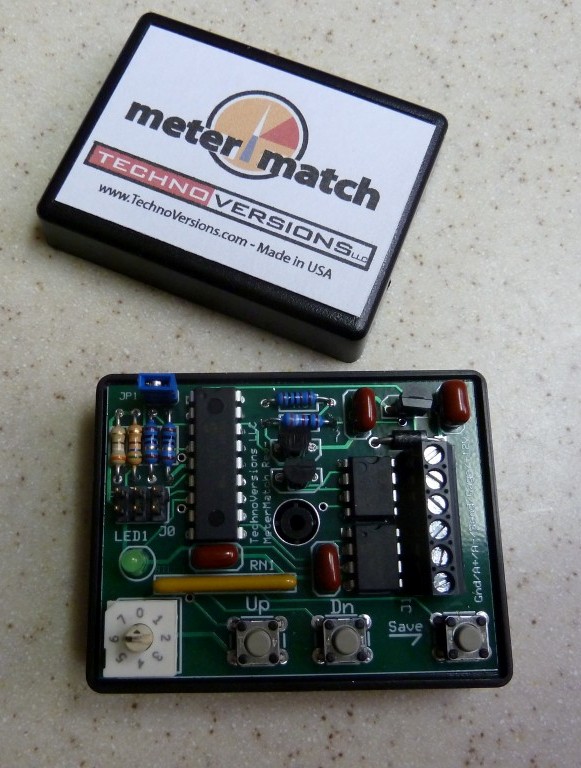
I likely explained in my earlier posts. The calibrator separates the measurement of the tank sender from the driving of the gauge.

To measure the sender a constant current of 20mA is supplied, and the voltage is measured using the A/D in the micro controller. Using Ohms law V= I x R, or R = V/I. By reading the voltage and dividing by current resistance is measured. The important part is to know the resistance at empty, full and in between. The exact values can vary based on sender, and float travel, but the calibrator can adjust for that.

About gain and offset. Perhaps you know slope related to the equation of a line. Y = mx + b. The m is gain, slope, or gradient (the steepness of incline), and b is the intercept.
The intercept is also called bias or offset. So Y is PWM value, x is sender resistance, b is Empty PWM, m is gain.

So to put in perspective the offset is the PWM value for the gauge to read empty, and for the correct gain the PWM will drive the gauge to full. /

The slope is actually negative or \, because sender resistance is less for full, than at empty.

Imagine having a plot of resistance vs sender travel, and a plot of PWM for gauge travel.
Then imagine a way to tie the endpoints together, and a function to generate the desired PWM based on sender resistance.
There is a change of resistance from empty to full, and a change of PWM from empty to full, m is derived by the ratio of those.

So the calibrator works by knowing the endpoint resistance empty, and the PWM value to drive the gauge to empty, and the resistance for full, and the PWM value to drive the gauge to full. The user pushes the buttons to generate the values for the gauge endpoints. The simple equation for a line, perhaps learned by most in 5th grade and long forgotten, is used to drive the gauge for all values between empty and full.

If this post is less than clear I am sure more can me found by entering "line equation" in a browser search field.
 
Kit, read the other thread. I have it working perfectly. The gauge is mechanically adjustable
 
Sorry I was a jerk to you in some of the posts. I guess if I did not have you to compete against I may have let it go by the way side.
 
It is OK. I never thought you were a jerk, or I was competing. I just like working with electronics and cars. I like you, work till the problems are solved, that is the reward.
 
I had a working Temp Gauge and tried to switch faces. That is when I paid attention to the inside of the gauge. Then is was like a light went on. Pulled my existing gauge and fixed it
 
thank you both for all your efforts. So if I am reading this correct all we need to do is adjust the stops thru the holes in behind the gauge?
 
I have a spare sending unit to work with and a variable power supply
Turn on the gauge with your 5vdc and add the 9.6 ohm resistance to the circuit. then see if you can turn the gauge all the way to the F mark. If it will not go that far, you may need to add some additional voltage. Mine worked great at 6.03VDC.
The sender should then be set to the empty position, appx 76 ohms +- 9 ohms, then if necessary turn the adjustment to put the gauge on the E mark (or just below it)

That is assuming you have a meter in good enough shape to do this with. Mine is
 
my biggest problem is it goes to empty when still half full. I write down milage every time I fill up
 
Then you should adjust the dial for the Empty setting.

One other item that I brought up earlier that should be addressed. My sending unit in the open air today in PHX, AZ was at a temp of 76 degrees. I ran the sender in the full position and am using 6.03VDC, not the 5VDC stock regulator.
Running in the open air, after 30-45 minutes the sender reached a temperature of 91 degrees. When in the car, surrounded with the gasoline, I highly doubt that it will raise the temp 1 maybe 2 degrees.
I feel this is safe enough for me in my car. You need to make your owned decision whether or not you wish to use the higher voltage if need be.

I think I need a disclaimer: I do not accept any responsibility for anyone actions, but my own. If you decide to make the modification to your vehicle as I described, you assume all the risk. I am not responsible if the 'fix' does not work or the car is damaged to any extent.
In other words; All information I have posted is for entertainment purposes only

Edward
 
Ed, I understand and when I get a chance I will try the adjustment. The ohms checked correct before I installed it in tank, thanks Joe
 
What happened to this thread. Is it dead??
I would like to hear the results of the testing of KitCarson's prototype.

I am still not happy with the way my gauge works. I am pulling the cluster in the next day of so. I am not sure I set the the stops right.
 
I sent the working prototype to 67dart273, for evalutation with real gauges. Since there was no rush, other projects have taken priority. That is OK.

While I used simple and proven means to solve the calibration issues at hand, most did not grasp the solution. The pressing of the calibration buttons, and connection of the 5 wires may escape many possible users. I am not sure if I can write an instruction manual, that everyone can folIow with certainty. I have no interest selling units.

I have provided a schematic above, if you wish to build one, I will send you a programmed chip. I will provide the code free for non profit use. I have no responsibility for the circuit or code, you are at your own risk.
 
Yeh, and I haven't had time either, LOL. I bought some Arduino boards and haven't done a thing there. I know very little about programming, used to play with basic a LONG time ago with a VIC20.
 
I do not know if I need it/want it or just want something to work on. i am willing to take a stab at it.
Can I get a parts list and whatever I need to work on it
 
feel like I need an engineering degree to understand this thread :( I just want my gas gauge to read accurately ,don't want to have to wire up controls for a NASA space station in order to do it
 
Kit this is really nice, but I will be the first to step up and say it. I would go into a complete and total mental meltdown tryin to figure it out.
 
It is simple.The circuit measures the sender resistances empty and full. By clicking the buttons, you drive the gauge to read empty, when tank is empty, and full, when full. Not hard, E clicks decrease gauge reading, F clicks increase. On exit the cal values are saved.

No need to calculate. No magic involved. It simply spans sensor travel to gauge travel. As long as the sensor resistance changes with travel, and the gauge can move from empty to full it will work. The gauge can be driven more if needed, because the sender is no longer in series. It can also drive gauge with zero, where the sender would have been feeding with about 70 Ohms.

The circuit values are on the schematic. Component values are not very critical, the calibration resolves those errors.
 
Actually, someone already produces a similar product. I'll re-rerrrrr reeee find it.........

EDIT

..............Found it!!!!

Someone had posted it on this board, but I don't remember where or who...........

http://www.technoversions.com/MeterMatchHome.html

"Meter Match"

Link to the destruction manual:

[ame]http://www.technoversions.com/MeterMatchVRInstructionManual.pdf[/ame]


Sounds very very similar to what Dave came up with
 
I don't mean in any way to take away from your efforts, Dave, but I'm tempted to get one of these and see how they do.
 
Thank you very much for your hard work on this Kitcarlson!!! You are very bright and it is awesome that you cared enough about your fellow Mopar enthusiasts to spend a lot of your free time to tackle this issue!

Thank you 67dart273 for helping out on this issue too. I just ordered the VR version of the device and will put it in my Cuda this summer. I appreciate you finding this product.
 
Heh, LOL. I'm not the guy who found this. I don't remember who, or I'd thank 'em. Someone else posted that thing some time ago in one of these threads. Please LET US KNOW how this works, 'K?
 
-
Back
Top