Not charging after HEI conversion

-

DropTopDart64

Member
Joined
Oct 8, 2023
Messages
13
Reaction score
7
Location
Colorado
I'm very new to electrical work so I very likely have done something wrong, but I don't know enough to know how to troubleshoot this myself so I'm looking for some help. I followed SlantSixDan's post on how to do this conversion and the ignition does seem way better now. It starts up much quicker, stronger sound from the engine, so I don't think I'm too far off the mark, but...

...after the conversion, my ammeter on the dash is reading well under halfway at idle. Prior to the conversion, it was charging strong just idling but now I have to rev it up to even get close to the middle of the gauge. I used a cheap relay with a built-in fuse from Amazon that probably isn't great quality, but the one I got from Autozone doesn't seem any different in performance.

I'd like to understand what's causing the problem, but also how to diagnose these kinds of things better myself if it's easy enough to explain. I've been researching things myself, but maybe I'm a bit slow to learn these days!

Pics below, I appreciate any help I can get!

EDIT: This is on my 225 Slant 6 since I forgot to mention it :D

HEI1.png


HEI2.png
 
Congrats on going to HEI, it is a great system. I do not see any reason/cause for your problem.

Maybe the alt or reg has failed at the same time you did the conversion. You do not need grd wires from the alt to body, the alt is already grounded where it bolts to the engine.
Your fan belt looks like it is rubbing on something...
 
I cannot see if/ where the alternator field wire is. Originally there should be a push on connector on the back, with a green wire attached. That should only go one place---to the F terminal on the VR. The VR IGN terminal should go to switched 12V AKA the same point as the key side of the ballast originally went.

So far as your HEI module, it needs a heat sink. I actually mounted mine--on my firewall--similar to how you did on your finder. You need to make sure it sits flat for heat contact, and recommended to use heat sink compound. Use star washers under the heads of the screws and do NOT use sheet metal screws. Use screws and nuts instead. Because of rust in the wheel well, and because of where you mounted the module, I'd reverse the screw heads--with star washers under the heads, and put the nuts on the inside. Use washers, also, under the nuts

Make certain you broke the little "tit" locating pin off the bottom of the module, if present.

ALSO WHEN IF you get the VR straightened out, (and I don't know why you chopped the wiring up so) I would make sure the VR IGN terminal is also fed off the switched output of your new relay

That is because voltage drop in the harness is a big cause of OVER voltage in these girls.
 
Last edited:
I don't know what's causing your issue, but your ignition module won't last long at all without some form of heat sink. I thought you said you followed slantsixdan's writeup. I can tell you that you did not. Why would you leave that out?
 
I cannot see if/ where the alternator field wire is. Originally there should be a push on connector on the back, with a green wire attached. That should only go one place---to the F terminal on the VR. The VR IGN terminal should go to switched 12V AKA the same point as the key side of the ballast originally went.
It's snaking around at the very bottom, Del.
 
Congrats on going to HEI, it is a great system. I do not see any reason/cause for your problem.

Maybe the alt or reg has failed at the same time you did the conversion. You do not need grd wires from the alt to body, the alt is already grounded where it bolts to the engine.
Your fan belt looks like it is rubbing on something...
Appreciate the info there, I'm happy with the ignition now, just not the charging lol and yeah that fan belt was rubbing on a radiator hose... Got the car a few weeks ago and I'm checking things off the list slowly but surely before its back on the road
I cannot see if/ where the alternator field wire is. Originally there should be a push on connector on the back, with a green wire attached. That should only go one place---to the F terminal on the VR. The VR IGN terminal should go to switched 12V AKA the same point as the key side of the ballast originally went.

So far as your HEI module, it needs a heat sink. I actually mounted mine--on my firewall--similar to how you did on your finder. You need to make sure it sits flat for heat contact, and recommended to use heat sink compound. Use star washers under the heads of the screws and do NOT use sheet metal screws. Use screws and nuts instead. Because of rust in the wheel well, and because of where you mounted the module, I'd reverse the screw heads--with star washers under the heads, and put the nuts on the inside. Use washers, also, under the nuts

Make certain you broke the little "tit" locating pin off the bottom of the module, if present.

ALSO WHEN IF you get the VR straightened out, (and I don't know why you chopped the wiring up so) I would make sure the VR IGN terminal is also fed off the switched output of your new relay

That is because voltage drop in the harness is a big cause of OVER voltage in these girls.
I appreciate the help, I need to double check the section on the VR from the guide I think, I'm wondering if that's the issue here. The field wire is in the little clip on the bottom side as Rusty said. I didn't chop anything up from the original (I think!), just ran the new wires from the pics and replaced distributor and coil. As for the heatsink, I've got some aluminum stock here that I'm going to fab up into a proper mount for it before it goes on the road, but the details there for mounting are great thank you!
I don't know what's causing your issue, but your ignition module won't last long at all without some form of heat sink. I thought you said you followed slantsixdan's writeup. I can tell you that you did not. Why would you leave that out?
Of course I must not have followed the guide exactly! but the guide does say some people have had acceptable results just bolting the module to the inner fender. That said, one thing I did forget to mention is that I haven't added the Fields Load Relay yet, so maybe that could be part of the problem too. I'd left that bit out for now because it said it would cause flickery charging, so I (maybe wrongly) assumed that I'd know that was the problem right away, but the charging seems steady, just low, but maybe I'm understanding that terminology wrong and that's the issue. Appreciate all the help, I've got some leads now and I'll let you all know how it goes.
 
Congrats on going to HEI, it is a great system. I do not see any reason/cause for your problem.

Maybe the alt or reg has failed at the same time you did the conversion. You do not need grd wires from the alt to body, the alt is already grounded where it bolts to the engine.
Your fan belt looks like it is rubbing on something...
I also just realized what you meant by the alternator ground... that label is a bit confusing in the picture, but that's the ground for the module that connects to the ground screw on the alternator case. The post from Dan said the body would be okay for a ground for the module, but that it was better to run a ground wire to the alternator or some other better ground.
 
Those modules absolutely MUST have a heat sink and they also have to have a high quality dielectric grease between the back of the module and the heat sink. This is absolutely, 100% necessary. Of course, as I said, this isn't the cause of your non charging issue, however, it WILL be the cause of your non running issue and soon unless you correct it. I wouldn't have mounted it to the inner fender like that, because they get hot enough to possibly damage the paint. Just because you saw something elsewhere on the internet doesn't make it right, or a good idea.
 
Actually Rob, I ran mine the same way--except mounted to the firewall under the wiper motor on what "seemed" like a flat spot. I did this sort of as an experiment--just to see if it would live. When the 67 was together, this was through a hot part of summer.
 
OP, turn your key to "run" with engine stopped. Probe the VR IGN terminal and you should have 12V there at that time.
 
Actually Rob, I ran mine the same way--except mounted to the firewall under the wiper motor on what "seemed" like a flat spot. I did this sort of as an experiment--just to see if it would live. When the 67 was together, this was through a hot part of summer.
Then run without a heat sink. You know what I always say. My car runs great. lol
 
93D3FD26-EDD2-4637-8697-8CFF0E6FBB2A.jpeg


4B29C9D7-B4FF-4B40-A72F-394E5C521FD7.jpeg

Make your own bracket. And I have to correct something from earlier in the thread, you don’t want to use dielectric grease on the module. You want to use hi temp heat transfer paste. It’s white and is important.
 
Not sure why you added all that wiring and relays to the back side of your alternator with your HEI setup, that wiring should be left stock. That is probably what is causing your charging issues.

Just use and E-Coil from like a '95 F-150 ford pickup, simple + - hookup spades and you run straight 12 volt to power it with no ballast resistor.

About as simple as it can get, and works great too.

Screenshot_20230615-030755_Gallery.jpg


Way hotter sparks than the round stock coils.

Screenshot_20230615-031217_Gallery.jpg

E--coil goes in line ^^^ where the yellow coil is pictured here.


☆☆☆☆☆
 
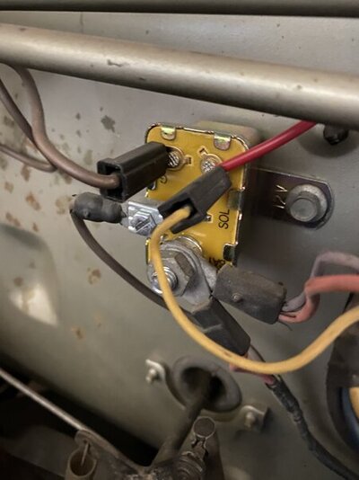
So maybe this is where I got mixed up and have a mistake. I haven't touched the original VR at all, but I've got that 86 pin from the new relay connected to the ignition relay like below (where the red tucks in with the yellow on the ignition pin). I'm planning to replace the VR as per Dan's post, but I wanted to troubleshoot the essentials to the system before I got too far into something I know very little about. But I did check and that pin on the ignition relay does not have 12V with the ignition on, so maybe that wire's in the wrong spot?

ignition relay.jpg

Have to love those plates!
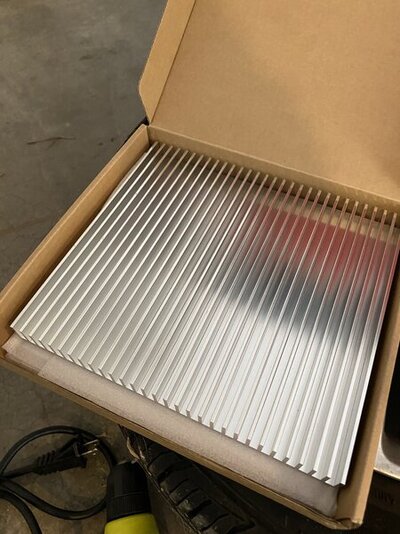
Those do look slick! Mine won't be quite as spiffy, but I've got this bit of aluminum I'm planning to slice and dice to make a fender mounted heatsink for it once I've got the wires where they need to go.

aluminum.jpg
 
Not sure why you added all that wiring and relays to the back side of your alternator with your HEI setup, that wiring should be left stock. That is probably what is causing your charging issues.

Just use and E-Coil from like a '95 F-150 ford pickup, simple + - hookup spades and you run straight 12 volt to power it with no ballast resistor.

About as simple as it can get, and works great too.


Way hotter sparks than the round stock coils.


E--coil goes in line ^^^ where the yellow coil is pictured here.


☆☆☆☆☆
There's only 3 new wires on the alternator: the ones going to the new relay on pin 30 and 85 as per Dan's post in the "Powers and Grounds" section, and one that grounds the HEI module case (from the "Module ground" section of the post). Like I said, I'm new to electrical work and I'm not afraid of learning from mistakes, but I did try to follow the post as much as possible to get the core of this system working. It's very likely that I've interpreted something wrong from the original post due to... well... not knowing much yet, but I did try to follow along with it.

I'm certainly not planning to tear out the coil I just replaced to go with the one you're suggesting since the ignition is noticeably better now. Before this work it would struggle to idle and as it stands now, it's running a thousand times better.
 
Some of yall have some nice installs under those distributors. The only thing I don't like about them is so far, I've not foune anyone who makes one piece connectors for them. Those single connectors just ain't makin it for me. No offence. lol
 
So maybe this is where I got mixed up and have a mistake. I haven't touched the original VR at all, but I've got that 86 pin from the new relay connected to the ignition relay like below (where the red tucks in with the yellow on the ignition pin). I'm planning to replace the VR as per Dan's post, but I wanted to troubleshoot the essentials to the system before I got too far into something I know very little about. But I did check and that pin on the ignition relay does not have 12V with the ignition on, so maybe that wire's in the wrong spot?

View attachment 1716155273


Those do look slick! Mine won't be quite as spiffy, but I've got this bit of aluminum I'm planning to slice and dice to make a fender mounted heatsink for it once I've got the wires where they need to go.

View attachment 1716155274
That'll work well!
 
I come from the PC/software world and thought about rigging up a gaudy LED liquid cooling rig just to get back at you guys for giving me a hard time about the current fender mount :rofl:
But while we're givin you a hard time, we're also givin you good advice. Seems like a good tradeoff.
 
-
Back
Top