fusible link testing

-

mopowers

Well-Known Member
Joined
Feb 15, 2006
Messages
8,544
Reaction score
4,750
Location
West Sacramento, CA
If a fusible link has continuity, does that mean its good? I imagine if a fusible link fries, it won't have continuity, right???
 
I'd like some more detail. So many guys are nowadays having trouble with the bulkhead connector terminals, and it is also possible to have problems at or in the ammeter

The SIMPLE answer is, if you have +12 at the battery and at the bulkhead where the link feeds in, you are OK that far.

"What ain't workin'" is my question

The hows, where's and why's:

http://www.madelectrical.com/electricaltech/amp-gauges.shtml
 
I'm not sure if the fusible links are multistrand inside or what but you need to do a voltage drop test on any questionable section of wire.

Measure the voltage from one end of the wire to the other. 0.2 volts "dropped" is about average. Anything more and there might be an issue.

Here's why: Picture a multistrand wire with ALL the strands broken and disconnected, except one single lonely strand. That single strand will register near-zero resistance just like any other wire but the wire will drop tons of voltage because it's forcing all the current through that single tiny little strand. Think of the wire as "using" up a lot of voltage just to force the current through that single strand.

You can see why this is bad, and you can see how it would fool a simple resistance test.
 
.................. you need to do a voltage drop test on any questionable section of wire.......................You can see why this is bad, and you can see how it would fool a simple resistance test.


That's a good plan but you left out one important piece and that is CURRENT. You cannot measure voltage drop without current flow.

One easy "backyard way" is to simply put as much system load on as you can, IE, with the engine off, turn the key to run, turn on heater blower, lights, etc, and then measure voltage, first at the "input," which is essentially the starter relay battery stud, and the "output" which is where the fuse link ends at the bulkhead terminal it feeds.

This is why, tho, that I asked for more details. Without knowing what the OP is fighting in the way of trouble, hard to advise.
 
I just bought a 68 dart that had the fusible link replaced with a 1' section of small gauge wire going directly through the bulkhead connector without using terminals in the Bulk head. The wire had a bare spot in it that arced on the gas pedal which melted out that section of wire. When that happened, the car died and would not turn over. I'm currently replacing it and installing a fusible link and replacing the melted bulkhead connector. I just want to make sure the fusible link I got from the JY is good before I install it.

Another things is, when the scabbed in smaller wire melted, I couldn't get the motor to turn on with the ignition switch even though there was continuity in that section of melted wire, which leads me to believe something else burnt up down stream. It would turn over by jumping the terminals on the starter relay- FYI

So, now I'm basically hooking up the new bulkhead connector with fusible link. Once I do that, hopefully I'll have power to the ignition switch. If not, maybe something else burnt up when the wire shorted out.

Any ideas? Am I going about this the right way?? Once I get this figured out, I plan on bypassing the alt gauge and installing a volt gauge.
 
New fusible links are available at any auto parts store in a variety of gages; you are looking for #14 gage. I would not bother with used links, keep in mind that links have a designed length required to dissipate heat for momentary overloads before opening circuit, special inflammable insulation that only melts, and will open circuit during a dead short.

You were real lucky the fire gods failed in their attempt to burn down your car; go buy a power ball ticket while you’re hot. LOL

Chrysler ignition has two independent circuits that interact to start & run engine: first is a start circuit that bypasses ballast resistor to feed coil with 12 volts when key is in start position only; second is run or ON circuit that takes over supplying energy to coil at reduced voltage at around 6-7 volts via ballast resistor once engine starts to keep from burning up coil.

Side note: This is the reason when ballast resistor fails engine will run as long as key is in start position, and stop when key returns to run or ON position.

Shorting starter relay with screwdriver will turn over engine no matter what position ignition key is in as long as battery, relay, and starter are connected.

You need to trace out the ignition circuits, and others following a wiring diagram to be sure that other wires were not melted & shorted out.

Check here for wire diagrams, and a lot of other information to help sort out the problem:
http://www.mymopar.com/index.php?pid=31
 
A fusible link is just a copper wire.

Fusible links are generally 2 gauges smaller than the circuit they protect. Made with fairly high temperature insulation that is a little thicker, sothat they look the same size as the circuit's standard wire.

They are only there to take care of a dead short - a 15% overload will not make one blow.

.

If there happens to be a dead short near that fusible link, is it possible for something else down stream (ie. the ammeter, ignition switch, etc.) to be damaged as a result???
 
Yes. Read the MAD link I posted earlier, which has a good explanation of the basics of the battery feed/ bulkhead/ charging wire and ammeter circuit

There are several main failure points:

The fuse link

the bulkhead connector

the ammeter connections or the ammeter itself

the in harness factory welded splice

the connector at the ignition switch

the ign switch itself

So far as accessories, problems in the fuse panel, loose / rusted/ corroded fuse clips or even "partially" blown fuses, IE which have been hot in the end caps due to poor connections

Once again, the MAD link:

http://www.madelectrical.com/electricaltech/amp-gauges.shtml

Useable but sometimes incomplete diagrams:

http://www.mymopar.com/index.php?pid=31

http://www.mymopar.com/downloads/1968/68DartA.jpg

http://www.mymopar.com/downloads/1968/68DartB.jpg

Our own factory shop manual download thread. Some of the earlier posted links are broken, have been reposted further down:

http://www.forabodiesonly.com/mopar/showthread.php?t=132309&highlight=manual%2C+download

Closest we have to your 68 is this 69 manual which should be very close

[ame]http://www.abodyjoe.com/pictures/Misc.%20car%20info/69%20dodge%20service%20manual.pdf[/ame]

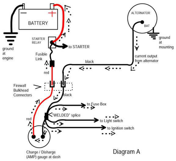
Simplified diagram from the MAD article:

Follow the red from the battery, starter relay, fuse link and to the bulkhead. Notice that it only goes to one place --- one side of the ammeter. If you can get a clip lead up there (with the ground unhooked for safety) and then hook the batttery back up, compare voltage at the battery to the voltage at your ammeter terminal with loads turned on, such as head lights. You should have very little drop, only about .3V (three tenths of a volt maximum)

Now follow the diagram through the ammeter and to the "welded splice"

Yes there can be bad connections at the ammeter or problems in the ammeter itself.

The welded splice is in the black ammeter wire, a few inches away from the ammeter, taped up in the under--dash harness. There is only one way to inspect it, and that is to cut / untape the harness slowly down from the black ammeter wire until you find it. These CAN AND DO fail in rare cases

This splice feeds different things in newer cars, but generally....................

branches off to headlights (only, not park / tail) power to the headlight switch

feed to the hot buss in the fuse panel

feed to the ignition switch

one/ two other things, depending on model.

Notice that NONE of this is fused except for the fuse link, which is damn poor protection, sometimes harnesses burn up before the fuse link pops!!!

amp-ga18.jpg
 
-
Back
Top