I asked on moparts too, but I just wanted some A-body confirmation.
I have the dash out in order to install my new one with volts, oil, fuel, speedo, and water temp. So no ammeter.
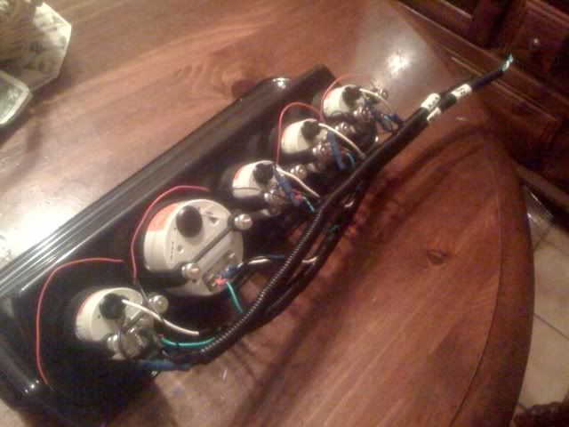
I am wondering how the dash is supposed to ground. The grounds are now all bundled into two ground wires as can be seen in this picture (the black wires). I was told the dash frame was the ground, but now that's not possible, so should I just find a good engine ground to ground it out?
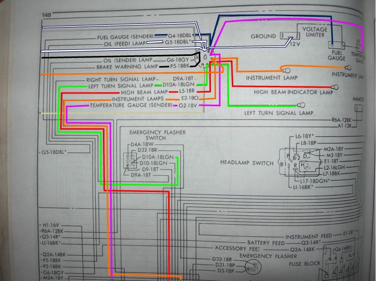
When I took off the leads going to the back of the ammeter, I forgot which post the red lead went on and the same for the black. I also wonder where these leads go now? Any insight?

I have the dash out in order to install my new one with volts, oil, fuel, speedo, and water temp. So no ammeter.
I am wondering how the dash is supposed to ground. The grounds are now all bundled into two ground wires as can be seen in this picture (the black wires). I was told the dash frame was the ground, but now that's not possible, so should I just find a good engine ground to ground it out?
When I took off the leads going to the back of the ammeter, I forgot which post the red lead went on and the same for the black. I also wonder where these leads go now? Any insight?