MOVING YOUR LEAF SPRINGS
Moving leaf springs inboard isn't hard to do, and doesn't take very long. You do however need to take care in measuring. The springs must be centered fore and aft, and side to side in the car. The biggest problem is that there are very few places on the car accurate enough from side to side that exact measurements can be taken. In the end, you want the rear square with the front wheels and centered in the car. The torsion bar mounts on the trans crossmember are really the only places on the car that are immobile and square with the chassis. Pretty much every other part of the car is either adjustable or inaccurate from one side to the other, which would make your measurements wrong and the axle crooked. If you have the means to make a jig to clamp the car in, this would be very easy, but most of us(including me) don't have that luxury. So here, I'll explain the easiest and most accurate way to do it on a hard floor.
Make sure you position the car so that it can stay there for the entire job, and level it side to side. Use a plumb-bob to transfer a mark from your front measuring points to the ground, and put a dot with a marker - something that wont rub off easily. All of your measuring will be made from these two marks.
There are two different methods of installing the front box. First is cutting out only the bottom and inner sides of the frame rails, and the second is cutting both inner and outer sides.
Cutting Inner Side Only
Before the pic on the left, I held a straight edge on the bottom of the frame, and held a square off of that edge in order to have a square cut with the frame as a whole. I made my vertical cut flush with the spring mounting pad on the outside. The exact positioning of this box is completely up to the builder. Also, it was suggested to me, and it seems better, to leave the outside wall of the frame intact to keep some of the rigidity. Note the existing hole in the frame...dont worry about it, as it's not really in a usable location.
Trial-fit the box and grind where neccesary to achieve a tight fit. DON'T weld it in yet. The spring-eye holes should be marked and drilled out of the car. You can also scribe a line on the outside to trim to match the side of the framerail. also note the gap at the red arrow. I trimmed the sidewall at the bottom of the box and bent the piece over to cover the hole, and welded it up solid.
To mark my spring holes, I dropped a plumb bob to the floor from the stock spring eye center and put a mark. I did this on both sides of the car, then drew a line across the two marks. Next I dropped the plumb bob from the side of the box to meet the line and marked the string location on both sides of the box. This gave me identical fore/aft locations as the original springs. Up and down doesn't mean a whole lot, as long as both springs are equal. Just measure up from the floor the same amount on each side, similar to the stock height. It's important to make sure you mark the exact position of the box, so your holes will be correct when you put it back in. Also you can drill a hole in the outer frame side and use a locating bar as shown below. Then I just took the pieces out and drilled holes and trimmed the sides on the bench.
After drilling the holes and trimming, I clamped the box back in the frame, using a magnetic level to keep the box square vertically. The box should be welded solid all the way around. Remember, it's holding your entire rear in.
All that's left is the shackles. Theres an existing hole in the rear of the frame rails, which, if I do it again, is where I'll put the shackle tube. It will require longer shackles, and the hole needs to be drilled bigger though. I drilled new holes slightly forward of this, but still on the inner plate. Just make sure you drill the holes STRAIGHT. It's hard with the spare tire well in the way. Slip in the tube and weld it up. Now you can bolt the springs in. This procedure actually moved my springs 4.25".
Cutting Both Sides
Here you can see the entire frame is cut to allow the box to fit in.
Again, it's basically just hold the box up there and scribe a line.
You should take care though to make sure you cut it right the first time...the better the fit, the easier it is to weld in.
With the frame cut, you can hold the box in, and using the method above, locate the spring eye centers for drilling. After they're drilled, you can align the hole with a bar as shown. Now you can see exactly how the box needs to be welded in. If you have air space between the box and the rail, you can box the frame in to make up the difference for a better fit and easier welding.
Here, you can see the importance of checking the alignment.
If you welded the box square with the bracket, the springs would be way off. The spring eye holes are whats important, and it's not worth eye-balling them and possibly having to cut the box back out.
Hold the box in position and tack it at all corners. Re-check the alignment with the bar, and if everything is good, weld it up solid.
Whichever method you choose, you now have a solid front mounting for your springs.
Shackle Mounts
The rear shackles are quite a bit easier. Theres an existing hole in the frame, which you need to enlarge to fit the tube. It's not easy , as theres a reinforcing bracket inside the rail that makes grinding difficult. A die grinder is about your only choice. Since theres already a hole there, a hole saw wont work. Rick Kreuziger says he welds a small tab of metal over the hole that has a 1/4" hole in it. This provides a pilot for a holesaw and Rick says this is the fastest method he's found to make a nice hole in this area. Once the hole fits the supplied tubes, slip it in and weld it up. Greg Zeneski chose to add large washers on the outside for additional reinforcement, which isnt a bad idea and also makes for a cleaner job.
And here's the finished mount. All thats left is to bolt your springs in and attach the new spring seats to the rear.
To locate the rear, first of course, put it on the springs with the new seats, unwelded. Now, drop your plumb bob from the end of each axle, on-center, to the ground and put a mark. Now measure straight forward to the marks you made earlier under the torsion bar mounts. These measurements should be equal. Next measure the diagonals ... left front - right rear and right front - left rear. Move the rear as needed to get these marks equal as well. When all these measurements are done the axle will be square with the front wheels and centered in the car ... which was the goal.
Now for one more thing...Pinion Angle. This is the relationship of the pinion stem to the transmission input shaft from a level plane.
If the two were on the exact same plane, the pinion angle would be zero. In other words, if the transmission was angled down, say -8 degrees, and the rear was angled upward 8 degrees, the two numbers, of course, cancel each other and the pinion angle would be zero - the trans shaft and pinion are perfectly in line such that a solid straight shaft could connect them without binding. But under acceleration, the pinion tends to twist upward. You must attempt to offset this twist to have zero pinion angle under the worst condition - hard acceleration. Most recommendations hover around 3-5 degrees down pinion to compensate for this twist. Which is zero pinion angle, then tilt the axle down an additional 3-5 degrees. In my own car, I simply welded the seats to the rear at the same angle as the factory seats. I haven't had any problems with it, but it could cause driveline vibrations if it's not at least close. I did it this way primarily because I was anxious to get it done, and pinion angle shims are available to achieve almost any angle, so it's not real critical to get it perfect while attaching the seats.
In case of a mistake, don't despair. My axle ended up being 1/8" to the driver side...this made the back of my car come around to the left when doing a burn-out. This is also the problem with cars you see on the road that look kinda crooked from behind. It's also harder to steer when the rear is trying to slightly turn the car and it wears slightly on the tires. The "true" fix would be to remove the seats and re-attach them. The professional way would be to get it right the first time. The more realistic "home" fix would be first, to drill the spring seat holes big enough to center the rear, then make two 1/4" plates the same size as the spring seats...like 2" x 4 1/2". Drill a 1/2" hole for the spring locating pin to fit in it. Place the plate on the spring, and the rear on top of it. Re-locate the axle as exact as possible, then tack the plates to the spring seats. Lift the axle and weld the plates all the way around. Be careful not to weld the plates while they're sitting on the springs...welding heat will ruin the springs. This now will place the rear in the proper location. It does lower the car 1/4", but it's much quicker and easier than the alternatives. Most cars of this nature sit a little too high anyway, which, among other things, alters the factory pinion angle, so the plates may actually cure a little of that.
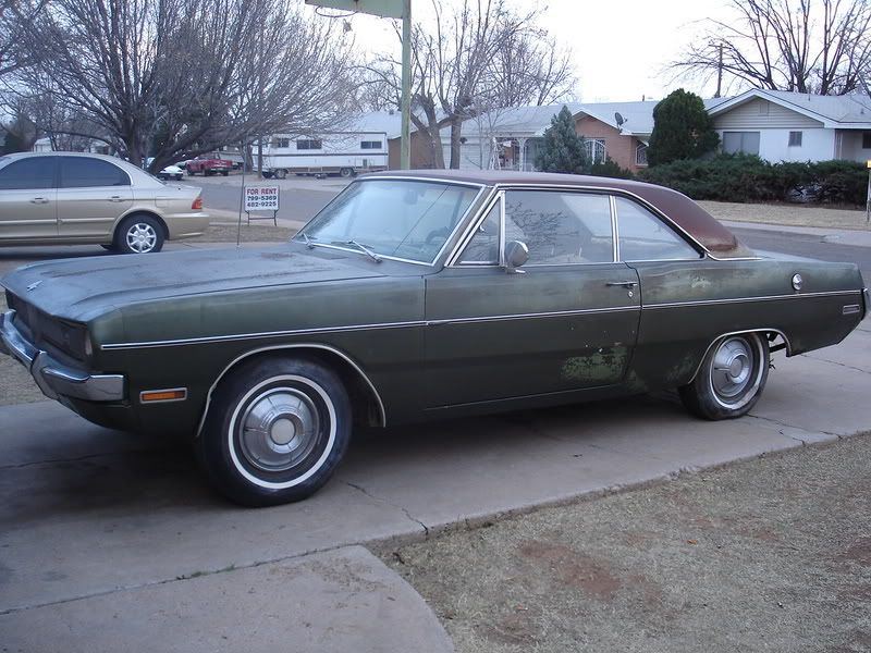
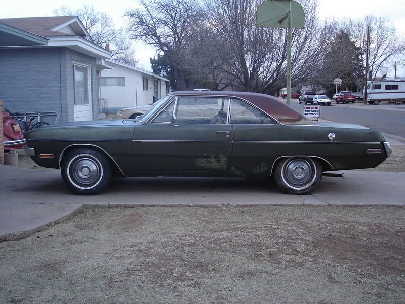
Prior to moving the springs and wheelwells, this was the biggest tire that would fit in my '69. As you can see, I can now just fit 12.5's in there. The difference is huge. This is the easiest and cheapest way I know of to fit decent tires.