Wanted: Tips and photos for installing 4-Speed Hump and Clutch Torque Shaft frame bracket

-

atedepumpo

Well-Known Member
Joined
Jun 28, 2024
Messages
54
Reaction score
40
Location
Virginia
I’ve reviewed lots of good information on this site and others, but any additional tips are greatly appreciated.

My first question is the easy one. Does anyone have photos of factory welds for the Torque Shaft frame bracket. I’m definitely an amateur welder, but hope to make it look as “factory” as possible.

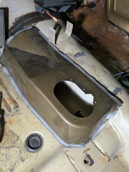
Regarding the 4-speed hump, my main concern is with the positioning of the front bracket for the console. In my picture, you can see grind marks on my used hump showing that the bracket was at least partially welded to the hump. Does anyone have a picture of the relationship of the console front bracket to the hump? I’m wondering if the bracket is still partially welded on the existing tunnel, or is the bracket totally on the hump when everything is positioned correctly. Maybe I’m overthinking this, but I don’t want to lose the positioning of the bracket. I’m wondering if I can maybe just cut the welds on the left side of the bracket (while leaving some of the factory weld on the right side of the bracket), and then slide the hump under the bracket so I don’t lose the position of the bracket?

Is there a known dimension between the front of the hump and the seam for the front of the floor pan? I guess I will mockup the transmission and shifter before final positioning of the hump. Did the factory use periodic tack welds, or maybe plug welds? Any other tips? Thanks.
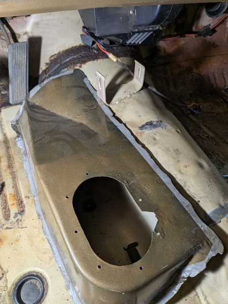
hump1.jpg


hump2.jpg
 
I’ve reviewed lots of good information on this site and others, but any additional tips are greatly appreciated.

My first question is the easy one. Does anyone have photos of factory welds for the Torque Shaft frame bracket. I’m definitely an amateur welder, but hope to make it look as “factory” as possible.

Regarding the 4-speed hump, my main concern is with the positioning of the front bracket for the console. In my picture, you can see grind marks on my used hump showing that the bracket was at least partially welded to the hump. Does anyone have a picture of the relationship of the console front bracket to the hump? I’m wondering if the bracket is still partially welded on the existing tunnel, or is the bracket totally on the hump when everything is positioned correctly. Maybe I’m overthinking this, but I don’t want to lose the positioning of the bracket. I’m wondering if I can maybe just cut the welds on the left side of the bracket (while leaving some of the factory weld on the right side of the bracket), and then slide the hump under the bracket so I don’t lose the position of the bracket?

Is there a known dimension between the front of the hump and the seam for the front of the floor pan? I guess I will mockup the transmission and shifter before final positioning of the hump. Did the factory use periodic tack welds, or maybe plug welds? Any other tips? Thanks.

View attachment 1716520013

View attachment 1716520014


Here's a pic of a Z bar support bracket posted by a member on here.

Factory 4-speed Demon


1773330380107.png


1773330399759.png
 

I’ve reviewed lots of good information on this site and others, but any additional tips are greatly appreciated.

My first question is the easy one. Does anyone have photos of factory welds for the Torque Shaft frame bracket. I’m definitely an amateur welder, but hope to make it look as “factory” as possible.

Regarding the 4-speed hump, my main concern is with the positioning of the front bracket for the console. In my picture, you can see grind marks on my used hump showing that the bracket was at least partially welded to the hump. Does anyone have a picture of the relationship of the console front bracket to the hump? I’m wondering if the bracket is still partially welded on the existing tunnel, or is the bracket totally on the hump when everything is positioned correctly. Maybe I’m overthinking this, but I don’t want to lose the positioning of the bracket. I’m wondering if I can maybe just cut the welds on the left side of the bracket (while leaving some of the factory weld on the right side of the bracket), and then slide the hump under the bracket so I don’t lose the position of the bracket?

Is there a known dimension between the front of the hump and the seam for the front of the floor pan? I guess I will mockup the transmission and shifter before final positioning of the hump. Did the factory use periodic tack welds, or maybe plug welds? Any other tips? Thanks.

View attachment 1716520013

View attachment 1716520014
Really simple. Drill 2 small holes through the bracket and into the tunnel. Then remove the bracket, fit your floor hump. Then line up the bracket on the 2 holes you drilled, and weld the bracket back on, then tack weld over the drill holes.
 
Really simple. Drill 2 small holes through the bracket and into the tunnel. Then remove the bracket, fit your floor hump. Then line up the bracket on the 2 holes you drilled, and weld the bracket back on, then tack weld over the drill holes.
Thanks. That's so simple, yet genius.
 
The factory ran weld beads about 1" long approx 2"-3" apart. Then used seam sealer all the way around to seal it up. On my 67 notchback I just welded it all the way around. I have no intentions of removing it. As far as how to fit it, the back end bumps up where the inboard FWD bucket seat reinforcing plate is. Use that as a starting point.

It would also help if you cut the sheetmetal in the floor away just enough to do a mockup of your 4 speed trans with at least the shifter tower installed so you know how far to the right or left to position the 4 speed hump. I used 2 different colored sharpie markers when I did mine. I traced the outline of the hump on the floorpan in RED sharpie, so I knew not to cut on that line. Then I drew my actual cut line in black inside the red line. The nice thing about cutting it out is you can trim the floorpan to give you a little additional clearance under the hump. Theres not much room under it for the rods and tower. This is why the reverse hangs under the crossmember.

Hope this helps
Matt
 
Last edited:
The factory ran weld beads about 1" long approx 2"-3" apart. Then used seam sealer all the way around to seal it up. On my 67 notchback I just welded it all the way around. I have no intentions of removing it. As far as how to fit it, the back end bumps up where the inboard FWD bucket seat reinforcing plate is. Use that as a starting point.

It would also help if you cut the sheetmetal in the floor away just enough to do a mockup of your 4 speed trans with at least the shifter tower installed so you know how far to the right or left to position the 4 speed hump. I used 2 different colored sharpie markers when I did mine. I traced the outline of the hump on the floorpan in RED sharpie, so I knew not to cut on that line. Then I drew my actual cut line in black inside the red line. The nice thing about cutting it out is you can trim the floorpan to give you a little additional clearance under the hump. Theres not much room under it for the rods and tower. This is why the reverse hangs under the crossmember.

Hope this helps
Matt
Thank you. Yes, this helps a lot.
 
-
Back
Top Bottom