AlV 69 Dodge GTS project

-
Nice pics and I love the detail. And thats a cool looking car.

That bezel around the ignition switch looks like a '67. In '69 they used a plastic bezel that was square around the key switch.

Some info, the 741 rear has a shimmed pinion (that is how the factory did it). What that means is you can swap the yoke with upsetting the pinion pre-load. Also looks like you have a cone sure grip unit.

The shifter handle is a pre '69. The '69s had a wood grain shift handle.

Year One sells outstanding reproduction wire harnesses. Not cheap but they are perfect reproductions of the original harnesses.

Looks like you are doing some excellent work love the write up.
 
I am going to take some of this info for my build. Check my thread out on my 69, its in my signature.

Nice car Rob! and I really like the 340 six pack setup you're going with.

I'm definitely going to follow your thread!.
 
Nice pics and I love the detail. And thats a cool looking car.

That bezel around the ignition switch looks like a '67. In '69 they used a plastic bezel that was square around the key switch.

Some info, the 741 rear has a shimmed pinion (that is how the factory did it). What that means is you can swap the yoke with upsetting the pinion pre-load. Also looks like you have a cone sure grip unit.

The shifter handle is a pre '69. The '69s had a wood grain shift handle.

Year One sells outstanding reproduction wire harnesses. Not cheap but they are perfect reproductions of the original harnesses.

Looks like you are doing some excellent work love the write up.

Thanks for following! This has all been great fun and an awesome learning experience so far.

I checked out your link ... Very cool and I like the way you set up the hoist to lift the car over the k member/engine and trans to install it. I'll remember that for the future!

Regarding some of your feed back (Big thanks for point them out):

I need to get a better picture of the 69 ignition bezel and shifter look like.
I'm wondering if I just need to replace the knob or if I have to look at the whole assembly.

You also mentioned that I have a cone style sure grip... which makes me wonder if that is a good type to have. I'll have to look into the different posi traction setups to get a better understanding of the cone type versus the others.

Also you pointed out that the 741 haad a shimmed pinion which I'm guessing is better than having a crush sleeve. I take that to mean that I should be able to replace the yoke with little worry of impacting the preload so it should be easier to set up. Do I have that right?

I'll add this to my list of takeaways for the future.
thanks
AlV
 
When I bought the GTS the AC heater control was not working and needed to be sorted out. I bought a used donor on Ebay for 5 bucks and salvage the slide lever and button covers. While I had it apart I cleaned the components, connections and connectors. I also touched up the button labels and cleared the vacuum ports.

With the Dash frame out I had unrestricted access to everything so I started the rebuild work with the Climate vacuum control unit. My approach to tracking the harness connections is to use masking tape to label the connections.

dash%2013_zpsn6mngq7g.jpg


dash%2014_zps3fgh4bmu.jpg


29586_447908301958216_1642616559_n_zpsucx8znoy.jpg


Other than being dirty the switch looked good.

58126_447908321958214_70438794_n.jpg


58126_447908321958214_70438794_n_zps3iuttfuw.jpg


Removal was quick and easy and I was certain to label all of the connections. Here you can see that wear on the buttons and the missing slider knob.

923305_447911038624609_1516911275_n_zpsxlxfy0si.jpg


Since my unit was in generally good condition I only needed to clean it up. I picked up a donor unit. My first step was to grab the slider from the donor along with any buttons and button caps. I also lubed the switch and push buttons because they had become very stiff.

417812_447908395291540_65455691_n_zpslotb4rr6.png


Here is a shot of the unit all cleaned and lubricated. It turns out that I need to grab the slide pivot clip along with the slide lever from the donor.

69006_447908358624877_899564786_n_zps0hzfns0i.jpg


I used a bit of white modeling paint to touch up the button lettering.

68569_447908728624840_1839834338_n_zpste4dynhr.jpg


I removed all of the switches and cleaned them up. The only switch I had to replace was the flasher since it had completely fell apart. Here is a shot of the light switch. A little cleaning, dielectric grease and done.

562577_448757188539994_1758942896_n_zpsvqimgrbk.jpg


The Radio wasn't working when I picked up the car. No power and wouldn't tune by either the thumb wheels or preset buttons.

936817_453234924758887_1430748187_n_zpsoppraztr.jpg


Some of the wires were cracked and needed to be replaced.

942045_453234911425555_432454142_n_zpsyqzwlkyb.jpg


I cleaned the electrical contacts and lubed mechanical contact points, including the thumb wheel torque shaft and gears as well as the chassis. I also address the button preset mechanism. I repaired the thumb wheel pinion gear located on the wheel itself and replaced the damage hold down spring with a safety pin trimmed to the same shape. the safety pin was slightly stiffer.

945962_453234914758888_1395448685_n_zps1nozrn4e.jpg


I bench tested the unit and happy to say that everything works as expected. I cleaned and polished it the beast I could and through it up on the shelf with the other finished switches and controls to reinstall later.

Next few pics show the tuner in different positions and shelved. lol.

603518_453234961425550_965558115_n_zpswvlib276.jpg


11827_453234964758883_1147855172_n_zpsgiwfulpf.jpg


While I was in there I did the ashtray but I'll spare you that one. lol

I'm sure that this could all be done to a higher standard but I'm really happy with it so far.

Next stop is the dash frame... Damage around the ignition switch and all of the rust by the glove box (damn that spark plug!)
 
Time to see what I can do with the Dash Frame. I'll straighten out the metal around the ignition switch. Then remove the rust. I put a piece of tape over the VIN to protect the plaque and stripped everything off.

This is how it looked before I did anything.

390580_454752217940491_1165537010_n_zpsn6f1x5ec.jpg


I figured that it would be best to start with the ignition area then move onto removing the rust.

397801_452913921457654_44111580_n_zpshnb1sz3c.jpg


Gave it a few whacks with a hammer and dolly. I also used a piece of Angle iron to bring the edge back the best I could. Then I used a file to flatten it a bit more.

310038_452913928124320_259647081_n_zpsxulugxnf.jpg


I sanded the area 60. 80, 180 applied of coat of Bondo. I cringe as I write this because I suspect an onslaught of criticism on the use of Bondo. lol Then more sanding 180 and 800.

941247_452913944790985_19252836_n_zpsnnlrpt6k.jpg


248038_452913934790986_1612346187_n_zpskrr9jv0q.jpg


943534_452913954790984_1870330786_n_zps2xmloaw3.jpg


Primer

182515_452913971457649_972259691_n_zpsvikjyoyi.jpg


I hit the rest of the frame with sand and steal then Primed.

262453_454752227940490_98609810_n_zpsoic57dio.jpg


Sanded with 800 then painted

247789_454752271273819_1879263417_n_zpsbdqpdnrd.jpg


945269_454752261273820_695068011_n_zpspwufx6m4.jpg


933995_454752281273818_1721913300_n_zpsrhnoyhso.jpg


With the dash frame done I set it aside for a while and took a shot at the bezels. This work was quit tedious and took a lot of time. the next few photos occurred over a few days. I definitely stumbled through this one. LOL. (WARNING, lots of pictures)

These are the consumables I used for this task.

260538_457184411030605_204731266_n_zps1v0t59ya.jpg


I started with the glove box dash Bezel because it was the cheapest to replace if I totally destroyed it. I read that I could strip the old paint without damaging the plastic by using brake fluid.

970243_457184014363978_1635820573_n_zpslwnxhqha.jpg


946889_457184001030646_189068012_n_zpsiicberud.jpg


970311_457184017697311_1846540905_n_zpsrssit2ve.jpg


247663_457184044363975_1221984639_n_zpsgpmhbg27.jpg


166057_457184064363973_2068730806_n_zps9t7lux7l.jpg


947130_457184077697305_1295643113_n_zpss20kdm8y.jpg


954724_457184111030635_1218768689_n_zps7ljsx1b7.jpg


247760_457184144363965_1186925360_n_zps8hbacz9g.jpg


I laid the piece on the dash frame to get a sense for what it would look like. I'm happy so far.

972344_457184151030631_966741749_n_zpsvawqzyww.jpg


I chose the AC/Heat and Radio bezel next. this one was a little trickier. I followed the same process.

263353_457184204363959_1781937905_n_zpsdlbff90f.jpg


65670_457184217697291_1159657293_n_zpswxkh8byl.jpg


253238_457184227697290_900938237_n_zpss4cm7gi0.jpg


229759_457184237697289_1648418851_n_zpsu5faefjd.jpg


65651_457184247697288_4253057_n_zps0p6m0qjw.jpg


21247_457184264363953_116393713_n_zpsubtw0d0y.jpg


945592_457184291030617_619150979_n_zpscsfc7ul2.jpg


601835_457184324363947_763195345_n_zps5qphkylp.jpg


With the center bezel done I did a another dry fit to see how it was looking. This time I took it outside. I've also started to add the controls back to the dash.

942615_457184381030608_1823059100_n_zpsupgrfj23.jpg


Followed the same process with the instrument bezel and dry fit all the pieces together. I'm feeling pretty good about the way they came out.

217342_457389814343398_1755395257_n_zps0yf5iaqq.jpg


done%201_zpsc6jxblw3.jpg


Time will tell how it holds up but in the mean time I'm stoked. The radio, ashtray and instrument cluster are ready to go in but before that happens I plan to sort out the harness. I received a donor harness from a 69 GT so we'll see how that goes.
 
That dash looks awesome!

Yes no crush sleeve on the 741, its a solid spacer with shims to set pinion bearing pre load.

Cone sure grips work good for a street car. But over time the cones bottom out in the diff housing then you will spin one wheel. When that happens stop driving it cause that mean excess slack in diff spider gears and cross shaft retaining bolt can shear and cross shaft comes out. Happened to me. With a cone sure grip suck that diff fluid out frequently and refill cause every time you go around corner its metal to metal.
 
Great work and great reading! I will be following and learning. Love the way you are clearly explaining each step, gives me some confidence to try on my own.
 
The '69 ignition switch bezel is plastic. Behind the dash is a metal bracket spot welded to the dash frame to hold the ignition switch and bezel in place.

Also pic of '69 shifter. I would imagine you could just change the knob.
 

Attachments

  • IgnitionBezel.jpg
    51.2 KB · Views: 1,227
  • Shifter.jpg
    61.5 KB · Views: 1,211
Nice pics and I love the detail. And thats a cool looking car.

The shifter handle is a pre '69. The '69s had a wood grain shift handle.

I don't know when the shifter knobs changed from chrome to wood grain, but my late built (5/69), 21k mile SURVIVOR MODTOP has the chrome knob.
 
I don't know when the shifter knobs changed from chrome to wood grain, but my late built (5/69), 21k mile SURVIVOR MODTOP has the chrome knob.

Dave brings up a good point about the build date. I probably should have posted the fender tag detail earlier in the thread. Looks like this GTS was built kind of early during 69 production with lots of 68 date coded parts on it. I can also tell you that my seats have no headrests which I think were made mandatory later in the 69 production run.

This is how my tag reads:

LS23:
Dodge Dart,Demon
Special
2 Door Hardtop

P9B: 340 275HP 1-4BBL 8 CYL
1969
Dodge Main, Hamtramck, MI, USA

143309: Sequence number

E55: 340 cid 4 barrel V8 275hp
D32: Heavy Duty Automatic Transmission
B5: Bright Blue Metallic Exterior Color
P6X: Trim - Premium, Vinyl Bucket Seats, Black
X9: Black Int. Door Frames
917: Build Date: September 17
118244: Order number

A04: Unknown Top Color
C16: Console w/Woodgrain Panel
C55: Bucket Seats
G11: Tinted Glass (all)
G33: LH Remote Racing Mirror
H51: Air Conditioning with Heater

J25: 3 Speed Wipers
L31: Hood/Fender Mounted Turn Signals
M21: Roof drip rail moldings
M25: Wide sill moldings
R11: Radio Solid State AM (2 Watts)
V1X: Unknown

V8X: Tranverse Stripes, Black
END: End of Sales Codes

Does anyone have thoughts on the V1X and AO4 codes they've come back as unknown?

Thanks Guys
 
Great work and great reading! I will be following and learning. Love the way you are clearly explaining each step, gives me some confidence to try on my own.
Thanks Scamper! Glad you find it helpful :D I'm just stumbling through and so can you! give it hell. lol

I'd like to see what your working on? Got a link or a pic?
 
Clearly I didn't think the dash frame project all the way through...I'm running out of space on the bench and I didn't think about where I was going to store the dash after it was dolled it up LoL. Note to self clear more shelf space. I moved stuff around to clear the top tier on my bakers rack for the dash but I was still not feeling comfortable about just laying the finished frame on the shelf. To address my concern I figured that a quick and dirty solution would be to make a stand. Thinking the stand w would come in handy for storage and make it easier to work on in the future. I took a ride to Home depot to pick up a piece of 10x2 lumber and came up with what you see here. nuthin fancy and wish I thought about it sooner.

IMG_4785_zpsyofruqtx.jpg


The dash harness is finally out and the donor was loaded with tons of goodies, it came complete with switches, relays, fuse box, light bulbs and connectors. Just looking at the two side by side and you can see the difference (top one came out of this GTS). Hopefully I can salvage what I need.

dc1bfd83-d488-4b15-b41b-d547f68b08e8_zps63092063.jpg


Now that the GTS dash harness is out I can really examine it.

395678_449299201819126_819548373_n_zpsalvfiksr.jpg


Outside of the Bulk head connector to engine bay illustrates heat damage.

5273_449297821819264_1316354158_n_zpsww3jxai2.jpg


Inside of the bulk head connector to cabin this is the wire that was splice to bypass the connector.

401264_449299428485770_1310481632_n_zpspljhczse.jpg


Cut ignition wires

431869_449297865152593_1278753746_n_zpsmtlqemds.jpg


My eyes aren't what they used to be.. And let's face it they were never that good!! So before I started I super sized the complete wiring schematic!! :glasses7: I used zip ties to keep the general shape of each branch of the harness which helped make it easier for tracing and applying the wrap tape later.

945192_459292264153153_1357715667_n_zpsfhp1buyn.jpg


The donor harness is completely traced, tested and labeled. I removed and cleaned the bulkhead connector and its ready to replace the damaged one on my harness. The red 10Ga. Wire was removed and can be seen coiled in the photo. The wire and connectors were cleaned and checked. I also removed the ignition wires to replace the cut and damaged wires on my harness. All items are ready to be transferred to my harness with the bulkhead connector.

972109_460841297331583_397048369_n_zpslmqbkzhr.jpg


I was having difficulty properly heating the 10Ga. Joints with the 40 watt iron.. I switched to the Big I mean micro gun to get it done. The Benz-o-matic micro torch worked like a champ. This is the only splice I made and it is for the ignition. Just have to wrap the harness and install it on the dash.

url]


Dash Harness...DONE! Yay! That was some fun right there!

1005555_468806693201710_251048178_n_zpsfkzpdbda.jpg


Ignition sorry about the gratuitous picture of my mitt ... definitely no hand modeling in my future...

969190_468806686535044_1677687586_n_zpstwb6tpxc.jpg


Inside Bulk head with replace wire and connector.

1010928_468806689868377_1774280843_n_zpsccjk45ps.jpg


Outside of bulk head connector ready for 43 more years. Yes I used a ton of dielectric grease but I spent so much time inspecting and cleaning each connector that I did want it to go to waste oxidizing while it sat waiting to be installed.

969950_468806716535041_739785373_n_zpsobkqigh5.jpg


I pulled the dash frame from the shelf to installed all of the components and the harness was the cherry on this finished task. Well I still need a speaker but hey I'm calling it done lol Here is a shot of the business side.

1017192_469660353116344_439830720_n_zpsusxcdn1e.jpg


Here's the party side

1010728_469291986486514_842393158_n_zpsjsrutdnd.jpg


Back on the shelf ready to go (whenever that will be I don't know)

You know how this works, now that I have the dash out I have such great access to the heat and AC. Before the dash can be installed I'll need to take care of the Heat/AC hardware and the wiper linkage.
Stumblin and tumblin hahaha!

Next stop heat/AC box, motors and coils. :coffee2:
 
Great job. I look forward to more. Nothing like a data log of progress. Keep up the fantastic work.
 
Outstanding work on that dash!


Great job. I look forward to more. Nothing like a data log of progress. Keep up the fantastic work.


Thanks, I really appreciate the encouragement! Just kind of winging it for the most part and hoping that I'll be able to refer back to this thread when I have to put it back together. LOL
 
There it is. first steps.

Started removing the heater and AC components. First the Heater side. I have the Rebuild kit and new Heater core on order. We'll see how this goes...

I went over it for a while to get oriented before I dug in. I must have inspected it for an hour. at least it felt like it was that long trying to get an idea of how this thing is built. Kind of like taking the time to smell the roses or something like that lol It really is an impressive bit of work, along lines of: "a fine mess" or "an accurate estimate" I've concluded the unit is "Complex simplicity"!

After realizing that this is not one but two separate sections (held together by one bolt which can be seen just left of the fan) acting as one I decided to start with the heater side first. The heater side is built like a clam shell with the two halves held together by clips. There is also a rod that runs up through the fresh air intake on the right that clamps to the cowl which need to be removed.

With the clips out I removed the front half of the shell to expose the heater core.

1002722_470342796381433_467736813_n_zpszyncnu9e.jpg


Then I pulled the back half of the box out next leaving the ac section which mounts to the firewall.

189874_470342789714767_1985766336_n_zpscj8inibm.jpg


Here it is in all of its glory, I can see the two halves, the damper contained in each and the heater core.

1001056_470342803048099_157351627_n_zpsisihlynf.jpg


181239_470342833048096_1052426139_n_zps5h2933cf.jpg


Next I pulled the AC section...4 mounting bolts and 4 Screws then the whole thing comes out. Since I was working alone I chose remove them in halves.

9355_472179639531082_1603817752_n_zpscqcirnqq.jpg


Perspective from the cabin.

1009892_472409226174790_1886378740_n_zpsdoofyzze.jpg


And the engine bay.

1044554_472409229508123_851570458_n_zpspkqj48gl.jpg


The Unit almost completely broken down. The two halves, the dampers, linkage, mixture control cable, the damper vacuum actuator, the fresh air holding rod. the heater core and the defrost duct.

936465_478061532276226_829760717_n_zpssehmxura.jpg


Here is the heater side all cleaned up a sorted. Waiting for the new core, foams and seals.

1013016_475927825822930_1819879610_n_zpstingyx3q.jpg


New heater core and sealer on the back half.

999687_484467994968913_1966438548_n_zpsw9vn8e2o.jpg


New Foams and sealer on the front half

1005212_484467988302247_1551527511_n_zps5kqqp5hy.jpg


Hers the completed half with new fresh air and blower foams also a cleaned blower motor resistor element.

1003469_484467978302248_1086487245_n_zpsrhkmlb75.jpg


Moving on to the AC side. Here's what it looks like Completely disassembled. Well almost everything. There is damper the resides in the air plenum tunnel to the left of the blower not shown in this picture because it's tricky to get to and I'm still working on that lol.

936465_478061532276226_829760717_n_zpssehmxura.jpg


I used a 2 1/2 in screw and coupling to make an expander in order to take out a very difficult to remove flapper.

1005102_480529475362765_398517323_n_zpswjvcbeyj.jpg


It's out! ... this is what it looks like... notice all the foam is gone.

1044419_480529508696095_1442643407_n_zpsvniyfslb.jpg


Cleaned primed and painted housing.

970424_480529515362761_1591862601_n_zpsydudjxzq.jpg


Seal putty applied to gaps on the seams of the AC box.

1002278_480529512029428_275668631_n_zpsvwxnunsj.jpg


970421_480529545362758_962828600_n_zpskm9xkbwv.jpg


Cleaned and cleared drain pan installed. Along with the damper fitted with new foam.

1013140_480529582029421_1704465917_n_zpsrykm4tqc.jpg


Cleaned and flushed Evaporator coil installed along with the thermostat and capillary tube.

945388_480529602029419_1165452596_n_zps6xtst3x2.jpg


Screens and sealer installed.

1013157_480529622029417_415346210_n_zpsrj6e43d6.jpg


Clean Thermostat, Vacuum actuators, cable, linkages and cover installed.

1044989_480529722029407_1482334082_n_zpskzbvohpz.jpg


Firewall insulation, gaskets and cleaned up blower assembly installed.

970954_480529678696078_1927206374_n_zpsebnszcug.jpg


Time to put the two sides together.

46289_484468381635541_141374036_n_zps1hit1bwe.jpg


1070081_484468388302207_1401483163_n_zpsbyujhnwr.jpg


Before/after

972209_480529478696098_246803295_n_zpsm6gscnns.jpg


Finished and going on the shelf until it's ready to go back in. I did check all of the vacuum actuators for proper function. I also lubed the contact points and used graphite on the cables. The vacuum lines were all good and cleaned up well except for the one that connects to the engine that one was hard and brittle.

998690_480529482029431_338562583_n_zpsbnzhkjs0.jpg


I had a lot of fun with this. I used the big kit from DMT which really worked out well.

Now that I've taken it this far and the front of the cabin is bare I think I should move on to the wiper linkage and pivot seals.

Oh boy...What have I done! :coffee2:[/QUOTE]
 
This was about the time I needed to shift gears a little bit and decided to take a stab at rebuilding the original A727. With the help of the awesome folks here on FABO I did Just that. Here is the link to the thread I started in the transmission and drive train tech section.

A727 Rebuild kits redux - Rebuild kits everywhere (62-70 vs 71+)
http://www.forabodiesonly.com/mopar/showthread.php?t=245164

I've decided to pull the rebuild portion into this thread... starting now... lol

Some points before I begin.
* The Video and handbook are valuable resources (a must have for any beginner).
* FABO members are very knowledgeable and have provided very solid advice

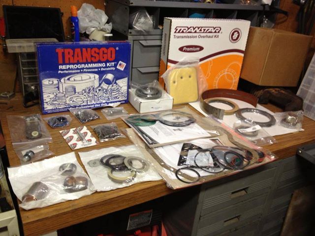
Once I had a handle on the parts, I sourced them from different vendors take a look at post 15 for the parts list:

Northern auto parts (http://www.northernautoparts.com) for the Deluxe rebuild kit by Transtar. When the Kit arrived I noticed the package read for 71 and up. I called the good folks at Northern and they said I was good to go with the 71 and up kit. I expressed my apprehension and they said that they would check on my concern and get back to me. While I was waiting for Northern to call back with an update I pulled up the Transtar website and when through the catalog. While on the website I found the number for their location in Edison NJ which is just 10 minutes from my work. I made a call to the Edison location and spoke with a nice guy there who explained that Transtar does not produce the 62-70 kit any longer and he suggested that I purchase the supplemental Kit containing the 62-up things I'll need. About 10 minutes after I wrapped up with Transtar Northern called back and said the same thing, they explained that is why the site indicate I need to purches the "K22950E-4" sub kit. All was good. So if you buy that kit keep in mind that you'll need to purchase the sub kit to if you are working on a 62-70 transmission.

TSR (https://www.tsr-racing.com) for basically everything else except the shift Kit.

Summit Racing (http://www.summitracing.com/) for the Transgo TF2 Shift Kit

kit_zpsde8627e5.jpg


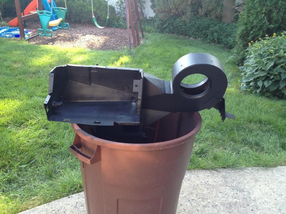
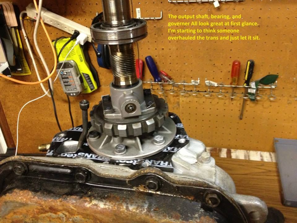
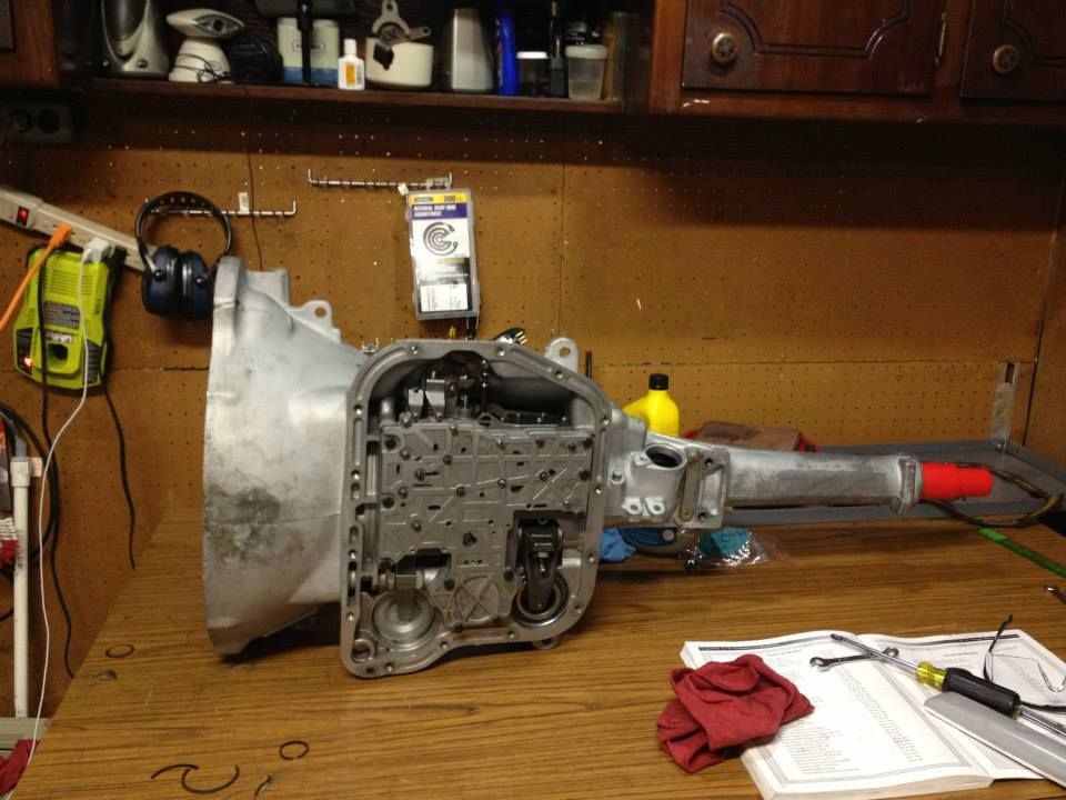
I removed the tail shaft housing and noticed it looked good.

tailshaft_zps6a3ae5d2.jpg


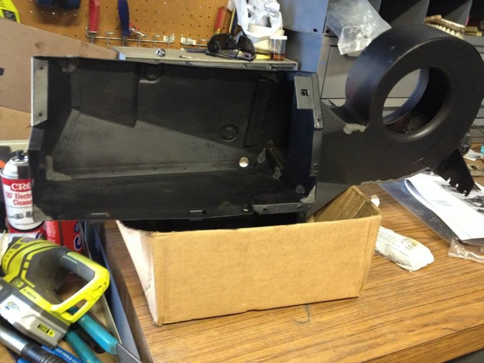
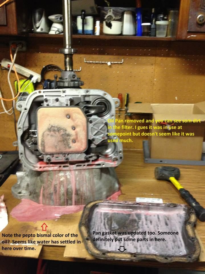
IT wasn't until I pulled the oil pan that I saw the pepto bismal... I don't know how long this trans sat out of the car but it looked like someone did a lot of work then let it sit.
pepto_zps0ed5d1ce.jpg


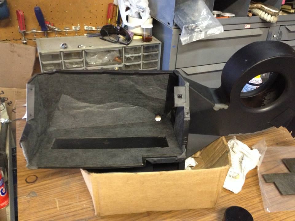
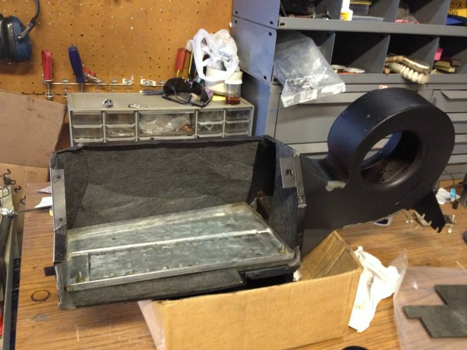
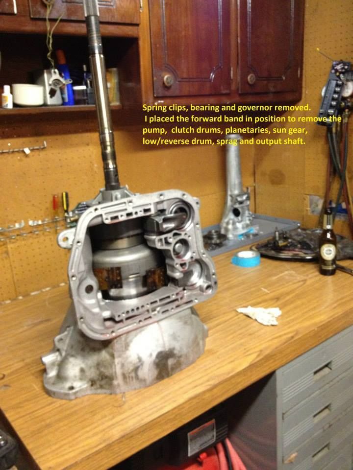
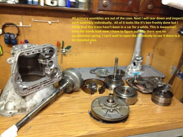
Taking the assemblies out of the case went smooth (slide hammers are key).
970531_498096420272737_914073706_n_zpsatugacc3.jpg


modules_zps924ebb8e.jpg


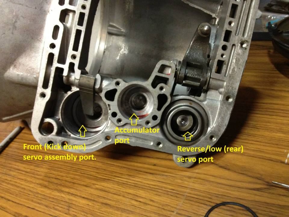
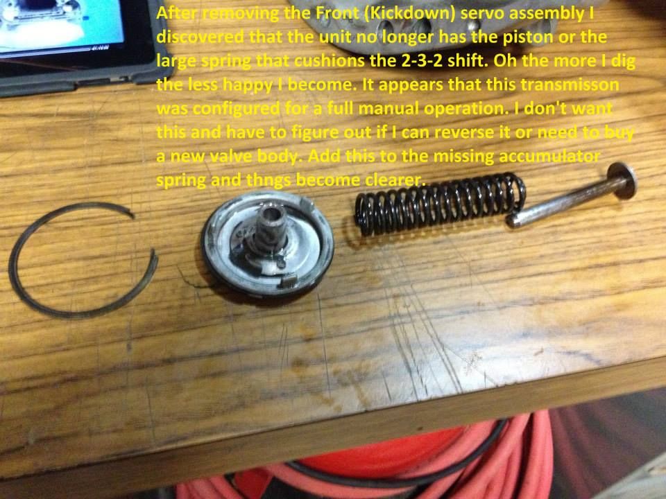
This is when it started to get interesting and more expensive. As I disassembled the trans I noticed that there seemed to be a lot of new parts as if it was overhauled run for a short while then pulled and set aside. As I removed the Valve body the first thing I noticed was that the Accumulator spring was missing and the piston was free to slam up and down in the port. I also noticed that the Apply (Kick down) servo was not complete either. So Now it hits me that this trans was prep'ed for full manual Race application and I need to bring it back to Street Auto. I can't wait to look at the valve body but I think I know what to expect.

servo_zpsf7a1e2a8.jpg


The Apply servo is missing the Piston and the outer spring (I picked up a new setup from (Pat Blais)

KD_zpsd3a63bb6.jpg


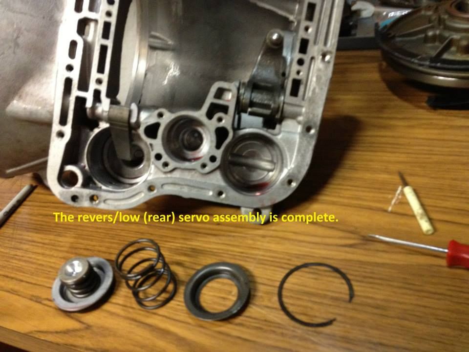
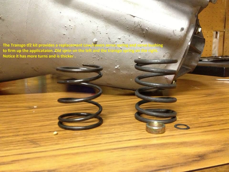
The Low/revers servo was left absolutely stock.

revserv_zps2a030889.jpg


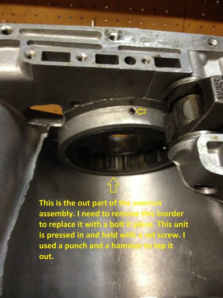
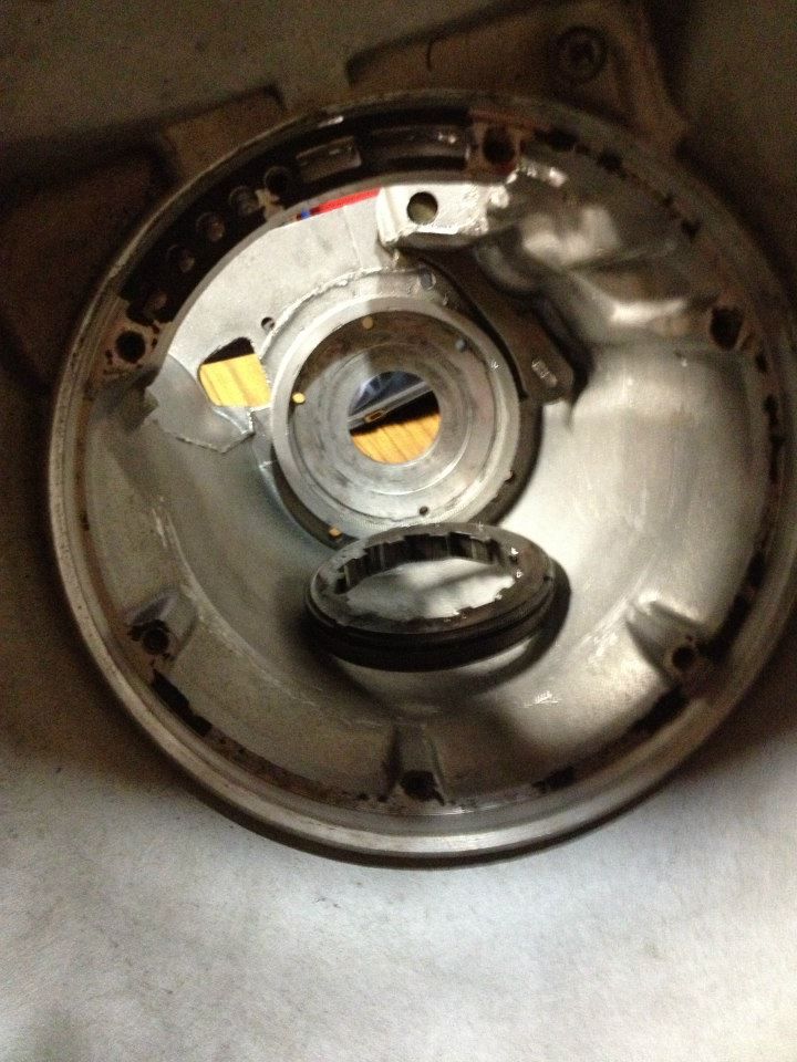
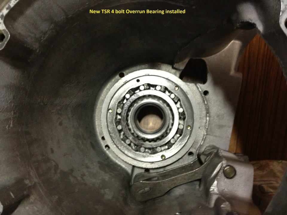
I removed the Overrun Bearing (Sprag) to replace it with a bolt in unit.

sprag_zpsefc68ef3.jpg


spragout_zpsf8f9622c.jpg


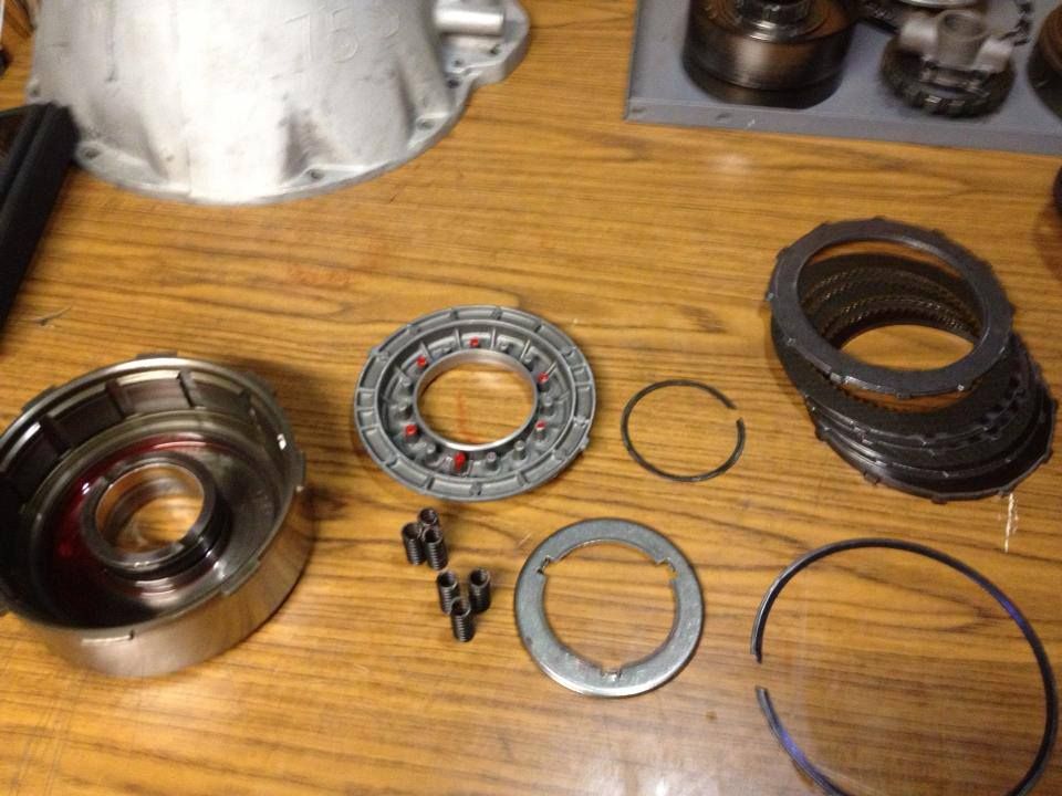
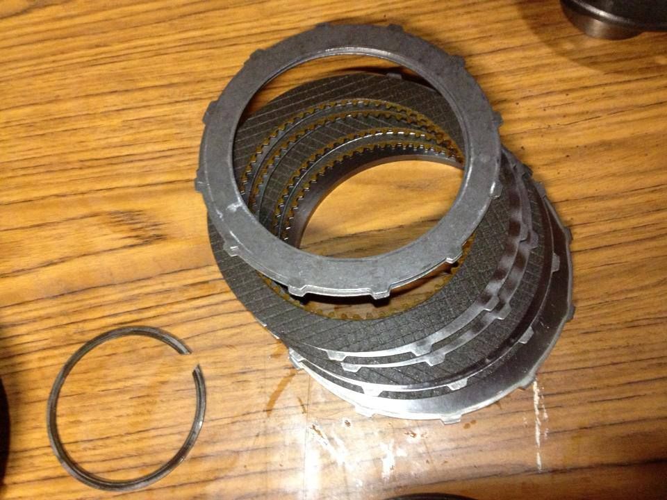
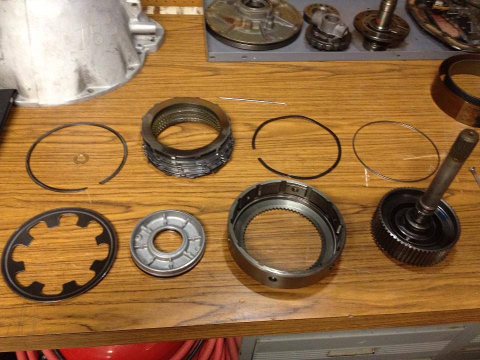
Disassembled the front clutch and notice that the frictions and steels looked barley used. Many folks have told me to replace them anyway since they've been sitting in water and well let's face it I didn't tear this down for nothing. This clutch was set up with the 340 spec 6 springs. I'll be upgrading to 12.

frontclutch_zpsfeab1a9e.jpg


frontfrict_zps912f7525.jpg


Moved on to the forward clutch and yess the material there looked the same as the front did and the bands for that matter. "shakes head"

forwardclutch_zps9a8f6501.jpg


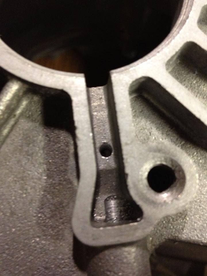
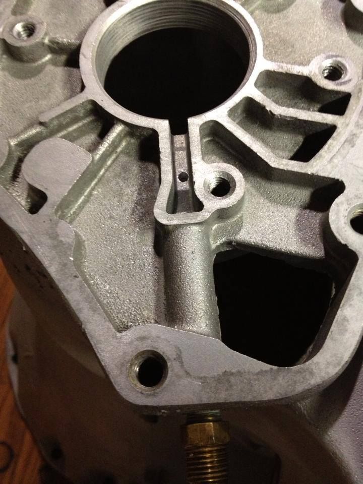
I drilled a 1/8 hole through the case on the oil return port as described in Munroe's handbook to provide additional lubrication to the bolt in overrun sprag.

8thdrill_zps0330efac.jpg


8thdrillbig_zps997fefc6.jpg


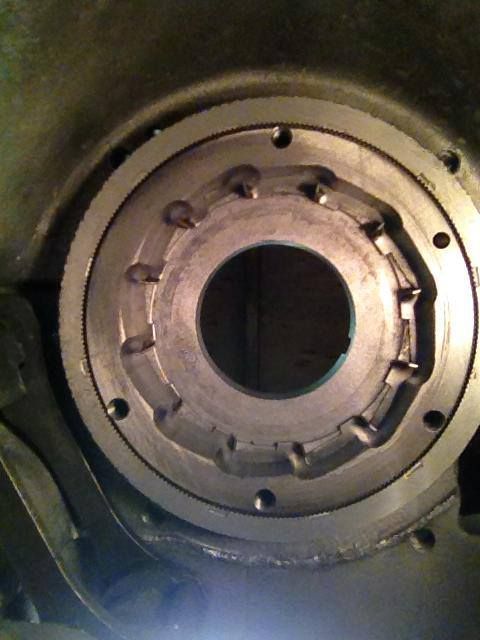
With the lubrication hole drilled and the metal shavings cleaned out I installed the bolt in overrun unit. I used the bolts to line it up and start it into the boss then finishing with a press. (A press isn't required but it sure makes it easier)

boltinsprag_zps6d6884bc.jpg


spragdone_zpsfc10621f.jpg


With the Overrun installed I reassembled (with all the new stuff) the pump, front clutch, forward clutch then did a Test
[ame]http://vid953.photobucket.com/albums/ae16/alv1970/2013-09-03112844_zps7a9702e8.mp4[/ame]
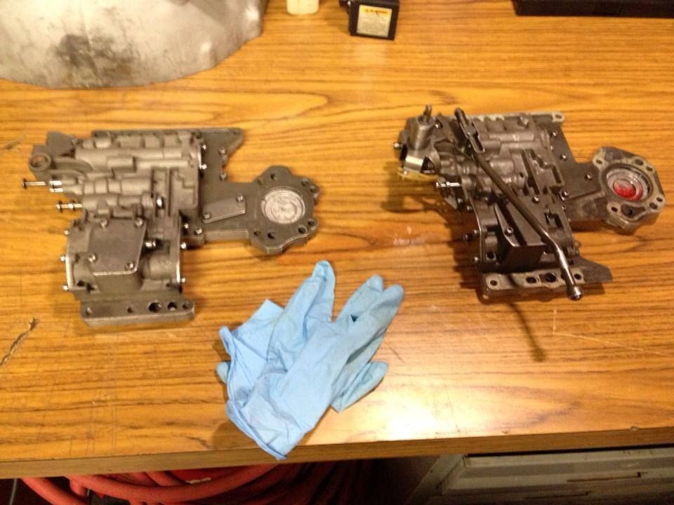
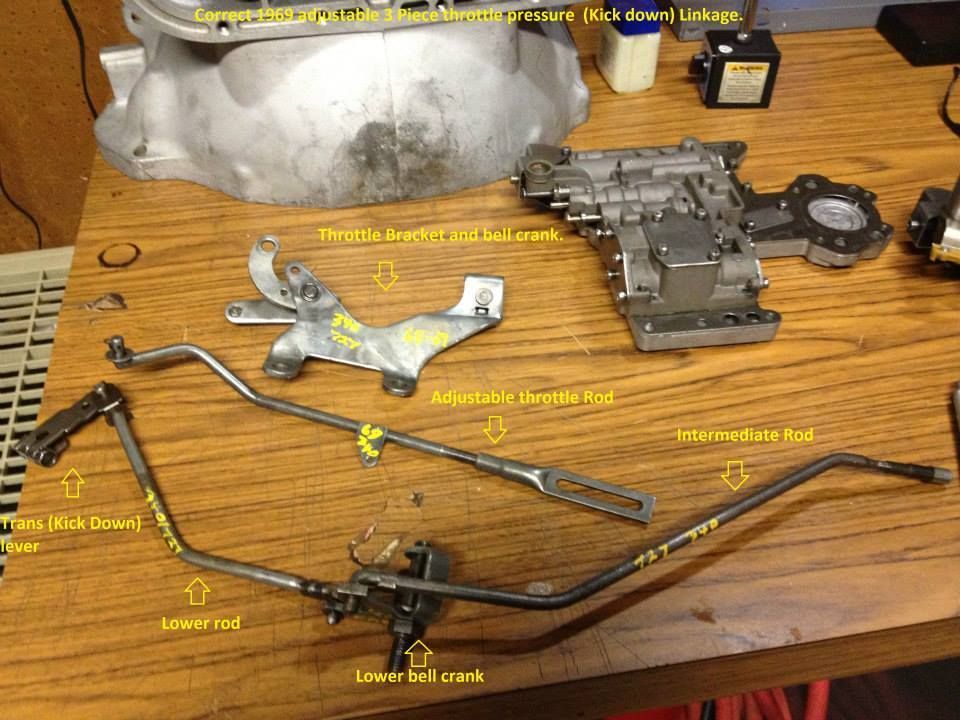
Here I wrap up the planetary, reassemble the drive line in the case along with the servos, then head on to the Valve Body. BTW I picked up an unmolested OEM 69 valve body (also from Pat Blais) which I'll use to install the Transgo kit.

Servos.. this is when I started using parts from the Transgo tf2 kit. The front servo goes in as it came out complete with 2 springs, piston, rod and retainer, except it has been cleaned, inspected and has new rings.

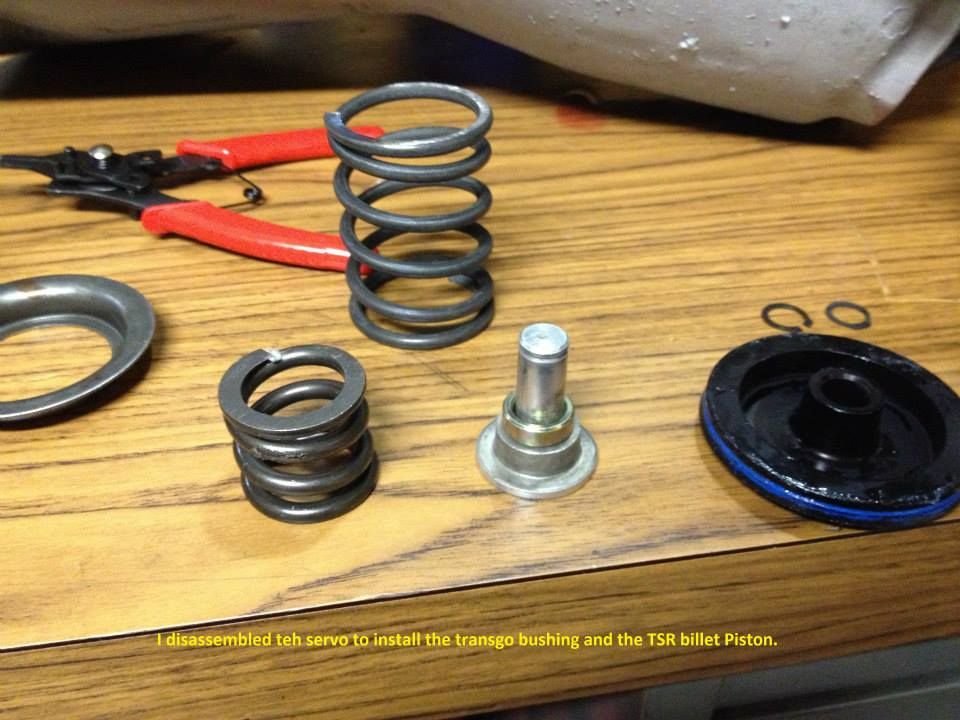
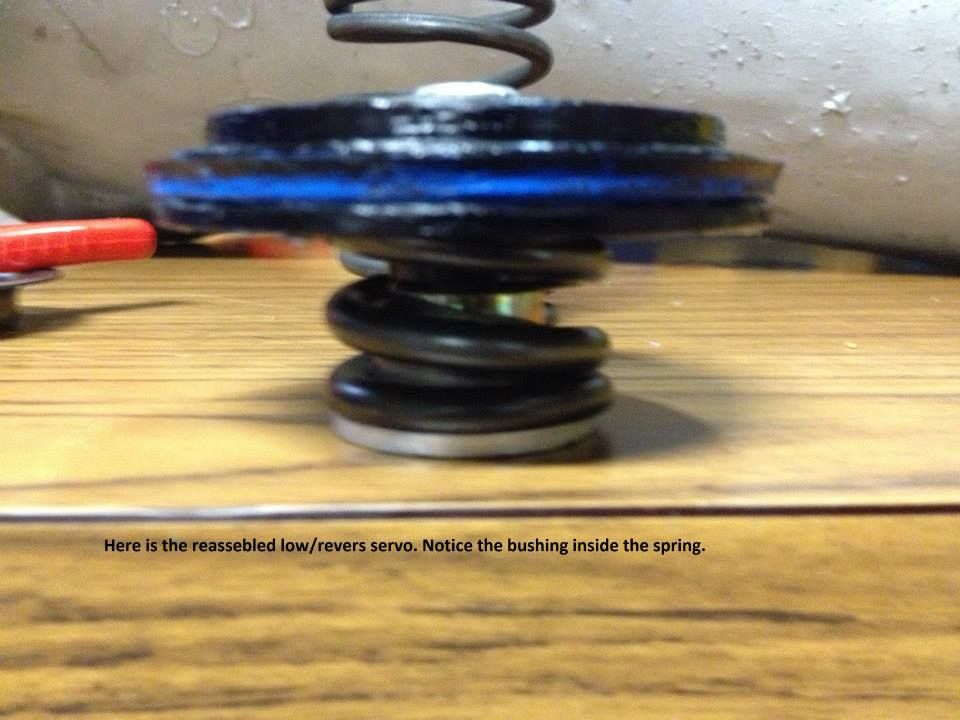
Rear Lo/rev servo is update with transgo pieces.

tf2springandbush_zps9db33cc3.jpg

tsrlorev_zps1ad03523.jpg

tsrlorev2_zpsf6bb3945.jpg


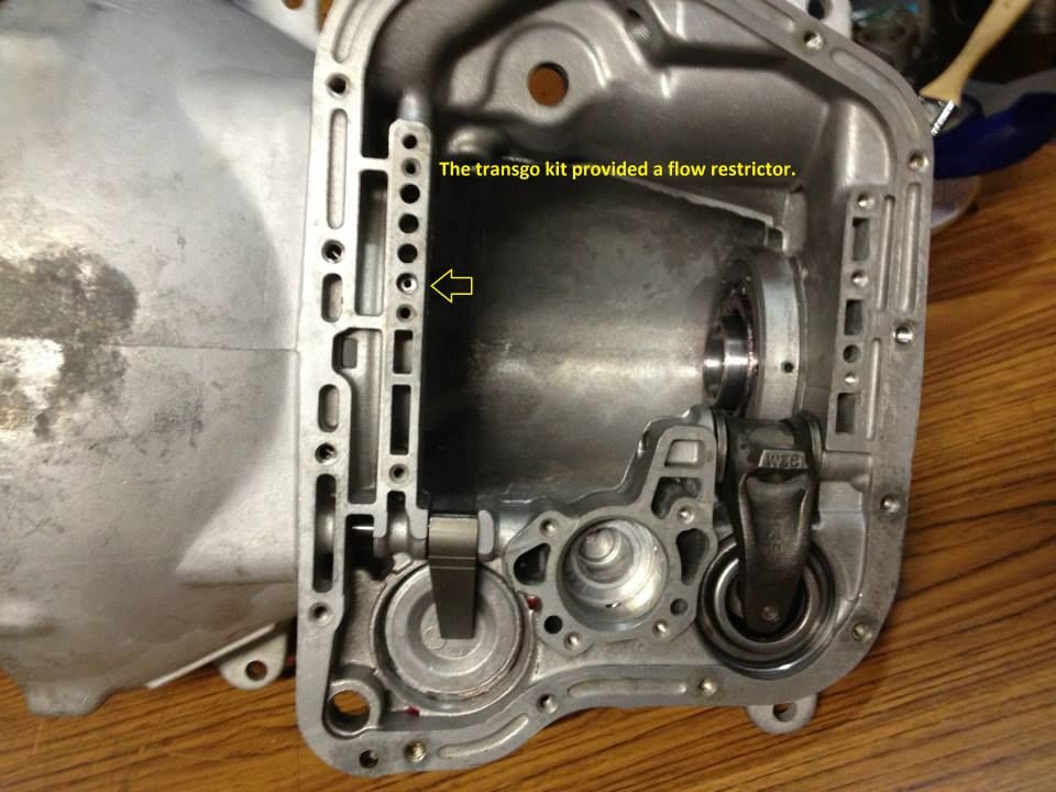
Transgo restriction plug installed

tf2restrictor_zps6711a723.jpg


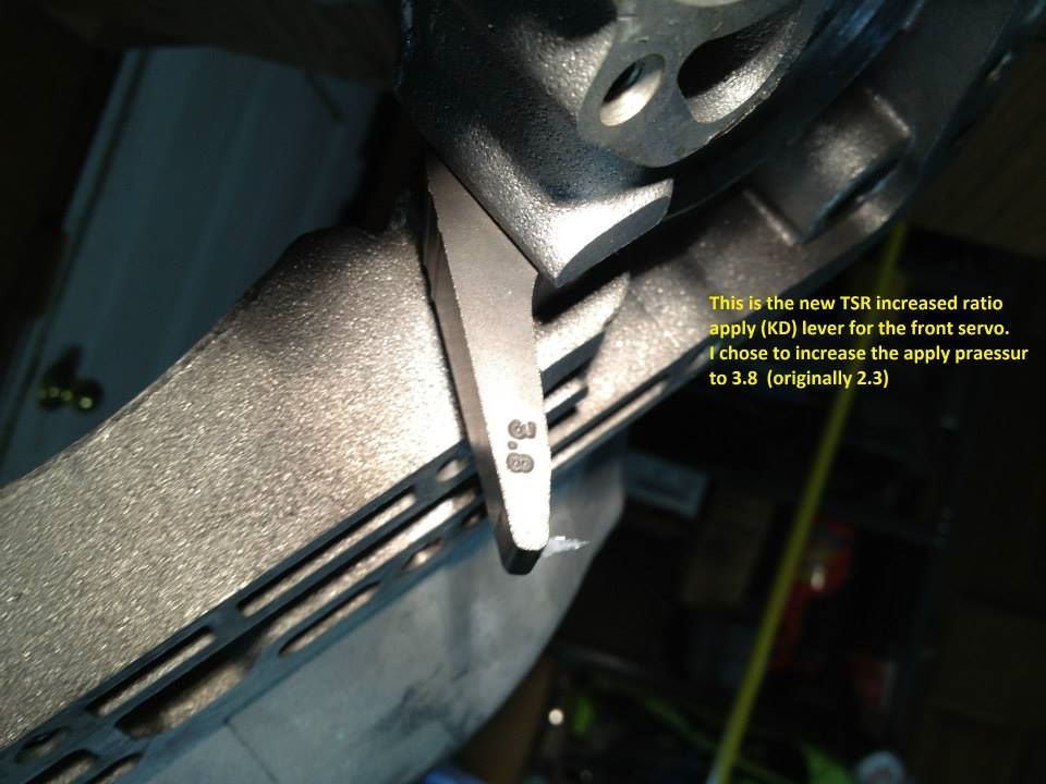
New front band apply lever

38KD_zpsc75ca6a8.jpg


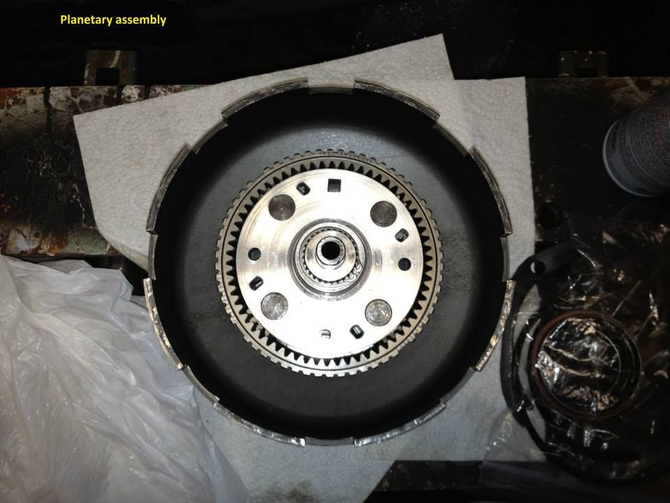
Planet is set up and ready to go in...

planetdone_zps21c75b9b.jpg


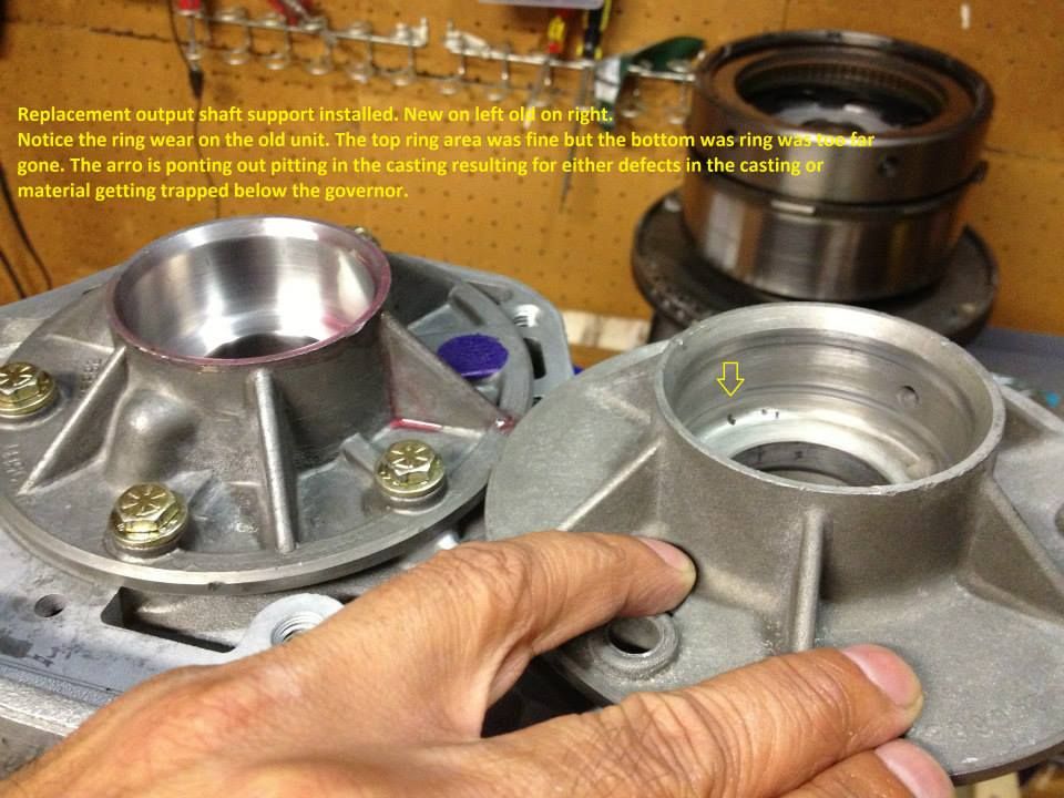
The output shaft support was pretty well worn in by the lower ring seal of the governor so I ordered a new one from Whatever It Takes Transmission [WIT] (https://www.wittrans.com) It's not a big deal if you are setting up for full manual but since I am returning to auto and I have it apart why not replace it.

outputshaftsupportdone_zpsc709907c.jpg


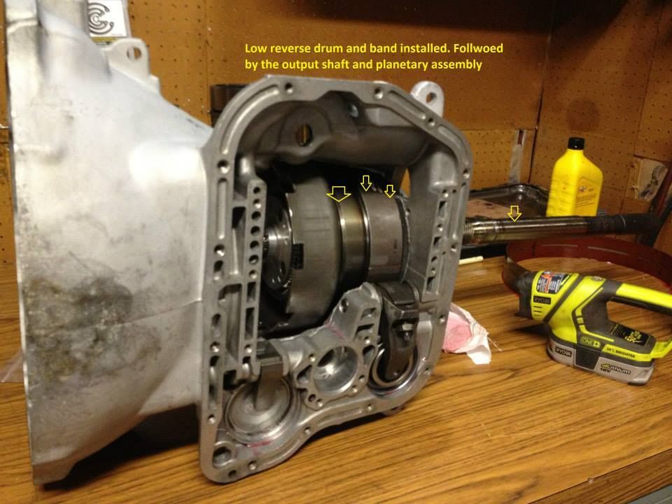
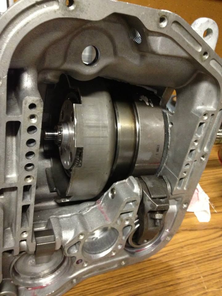
Low/Rev drum, band and planet installed in the case.
1240087_507137072702005_1563901332_n_zpsfo6zyyy3.jpg


lobandanddrumandplanetinstalled_zps9efa5e54.jpg


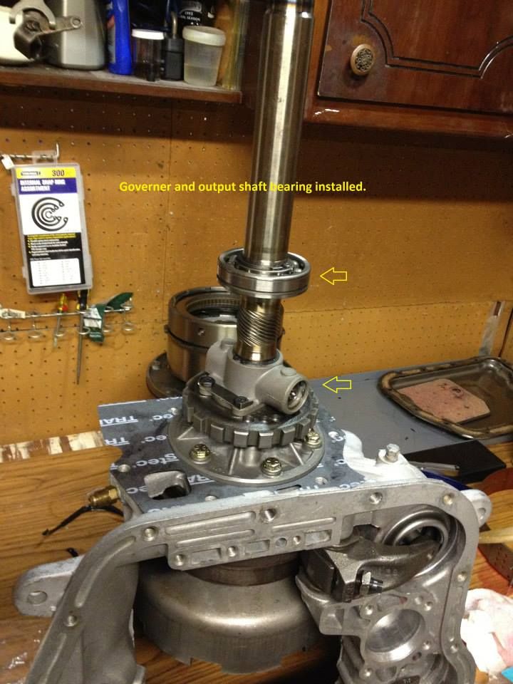
Next the Governor and bearing

govandbearing_zps7d2964c6.jpg


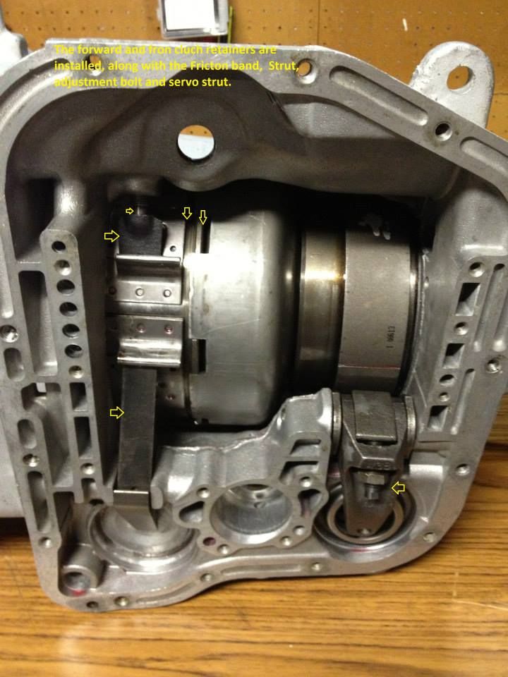
Next the input shaft assembly (front and rear clutch packs)

frontandrearclutchandbandinstalled_zps020210ce.jpg


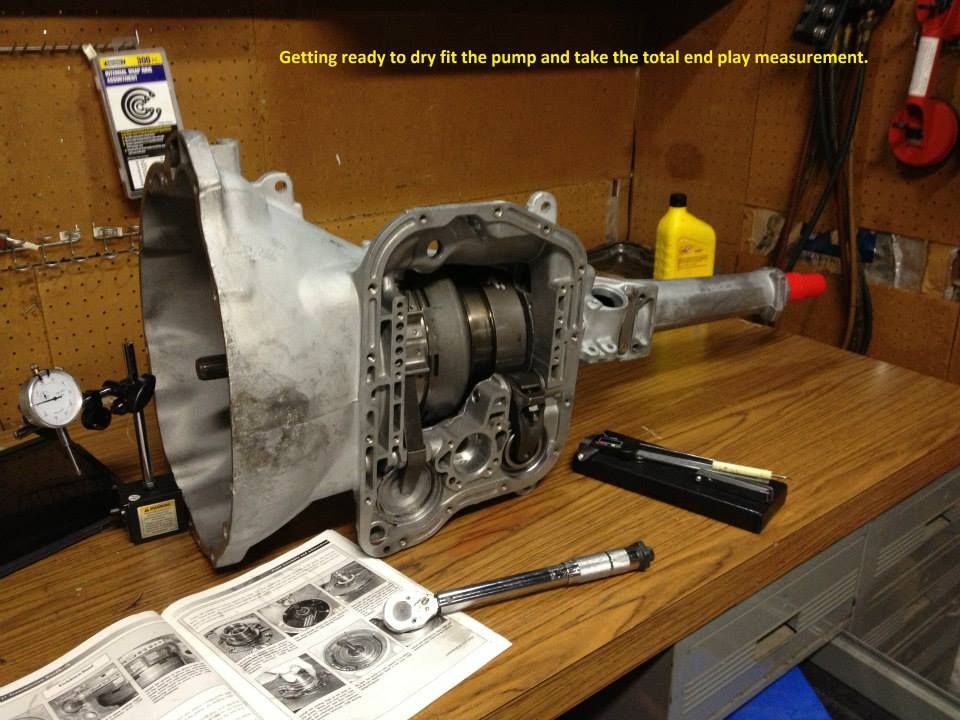
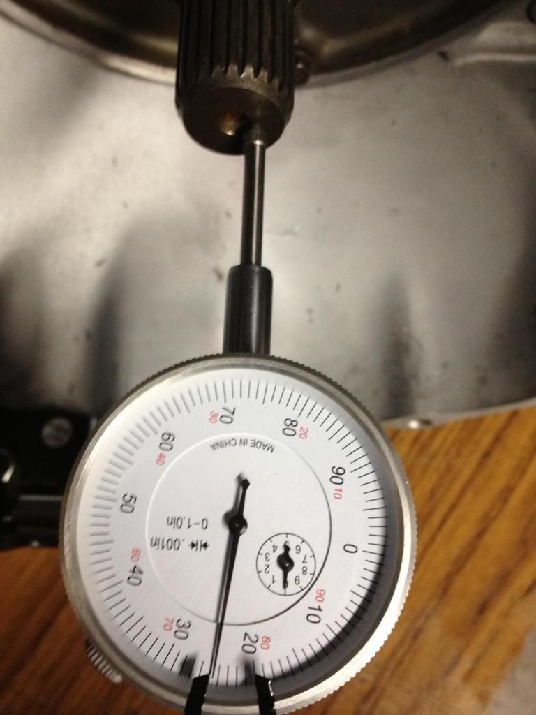
Time to dry fit the pump and take total end play measurements

pumptotaleendplay_zps0280cf7e.jpg


I'm stoked with this measurement

endplay2_zps3cf2134a.jpg


with a good read on the dial I put pump in with the new seals along with the tail housing then made the adjustments to both bands.

Next stop... valve body.

I hope to have a nice street setup when I'm done and I'm praying it all works and I didn't do something stupid! LOL

Here's a recap of the details of my final build:

My trans is set to the following spec:
1. Rear clutch pack clearance is .040
2. Front clutch clearance is .045
3. Planetary play is .025
4. Total end play clearance is .024
5. Front clutch pack increased from the 6 springs to 12
6. Front (KD) servo using both spring 45# inner/45#outer ( I have a 20# inner in inventory that can be switched in later)
7. L/R servo has the Transgo Spring and bush
8. Transgo restriction cup installed
9. Rear band adjusted to 3/8" of travel
10. Front band adjusted with small wrench to Snug then backed out 2.5 turns
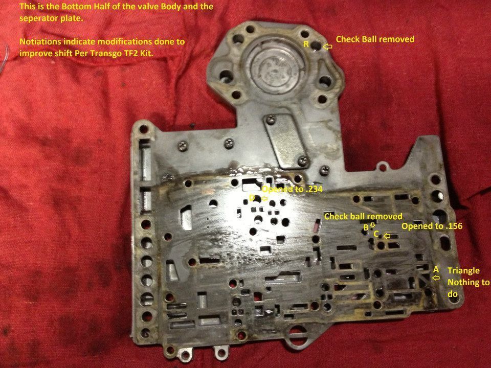
Transgo TF2 setup.

Part 1:
A. Triangle did not drill
B. 1-2 shift did not drill (ball left out)
C. 2-3 shift drilled to .156 or 5/32
D. drilled to .234 0r 15/64

Part 2:
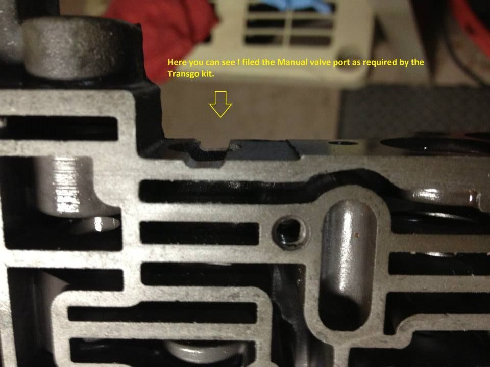
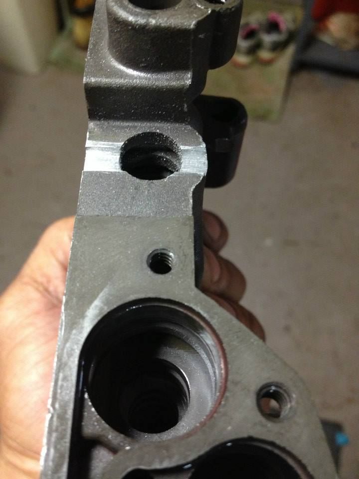
1. Re designed Manual Valve installed
2. Filed Notch halfway through manual bore
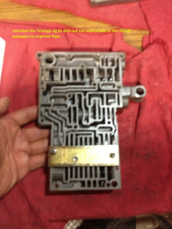
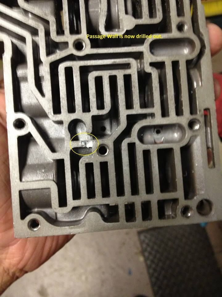
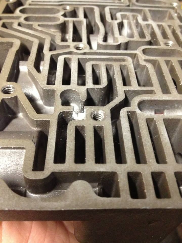
3. Drilled passage wall to increase fluid flow
4. Grind TV stem to .281 or 9/32 added yellow spring
5. Installed new shim and spring seat on PR valve, also added the new inner and outer Orange spring.
6. set PR adjustment flush against the inside edge of the spring retainer.
7. Installed new L/R Spring
8. Installed 2-3 restrictor cup

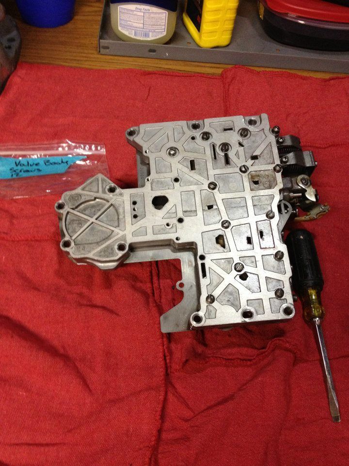
I picked up a spare Stock 69 Valve Body cleaned and ready to restore back to OEM spec.
1238918_508159049266474_1226717075_n_zpsidjqvxa8.jpg


999199_510485255700520_1925107600_n_zps61olafgv.jpg

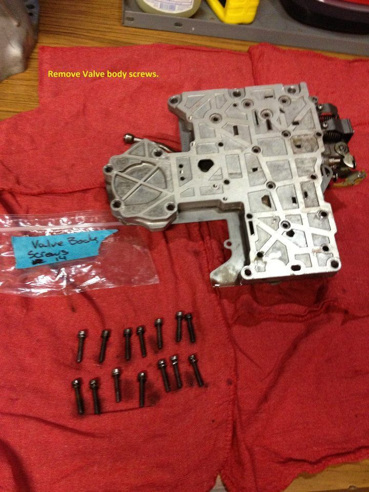
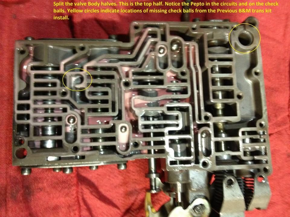
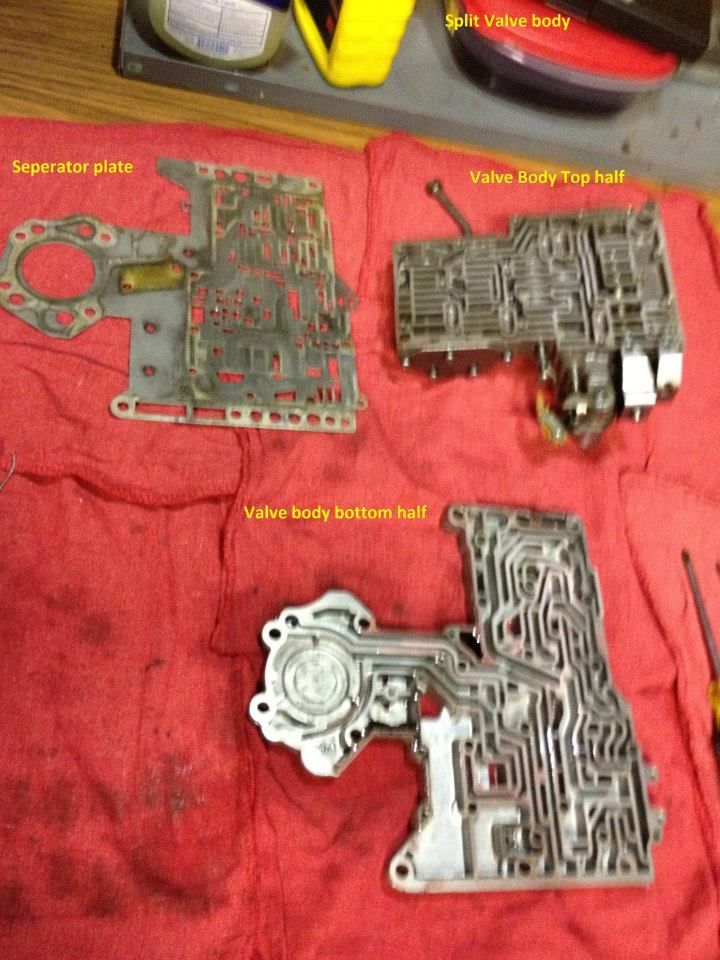
Split the Valve Body
999138_510485245700521_411685840_n_zpshsdex2gf.jpg


1234184_510485279033851_129253426_n_zpsjlab1ya5.jpg

1234961_510485289033850_1899811664_n_zpscu14mtwt.jpg


1187019_510485315700514_1591728547_n_zps7gqdigd5.jpg


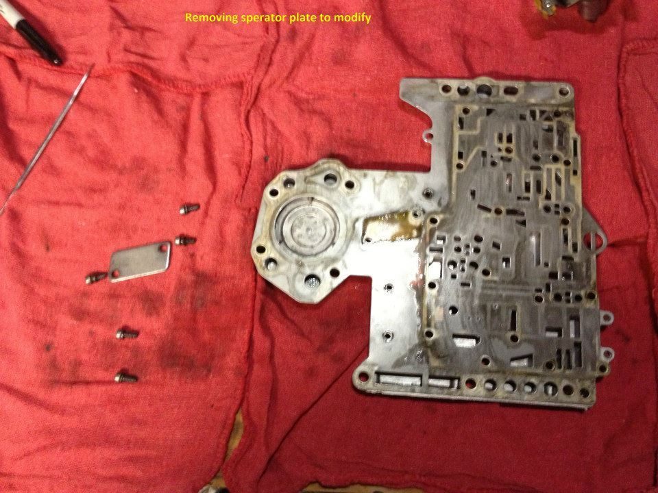
Remove separator plate and Drill.

1236007_510485339033845_1792075024_n_zpslfbmxlwc.jpg


560532_510485369033842_1703353824_n_zpsngv6qw49.jpg


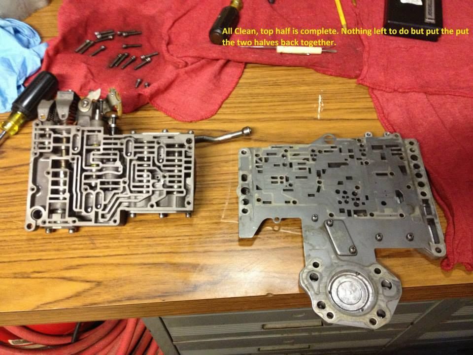
The valve body sandwich

1175174_510485392367173_552475342_n_zps7cdakggz.jpg


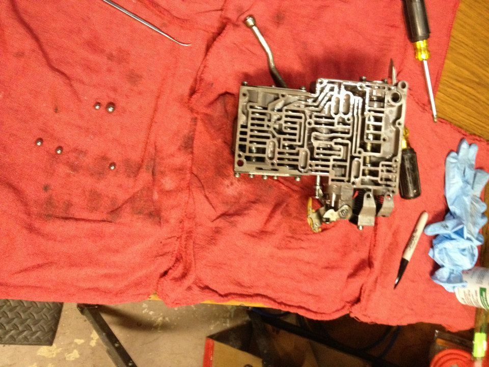
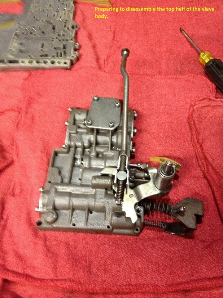
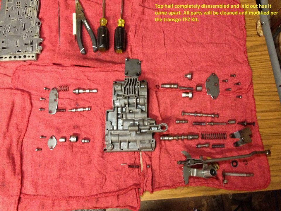
Working on the Top half

1234498_510485409033838_1527705219_n_zpsvau2jn5x.jpg


Before Transgo Mods

970433_510485439033835_290861426_n_zpsg1lxn9un.jpg


After Transgo Mods

531940_510485449033834_907354442_n_zpsc5are6fl.jpg


59352_510485495700496_1128311539_n_zpswjfpmb98.jpg


1236088_510485519033827_1902664586_n_zpsptmqbgpy.jpg


1231260_510485535700492_92604950_n_zps6ecfyopi.jpg


1185796_510485565700489_77426592_n_zpsekaqefls.jpg


Updated Manual valve, springs and TV grind.

563525_510485585700487_720552848_n_zpscvtfxnsf.jpg


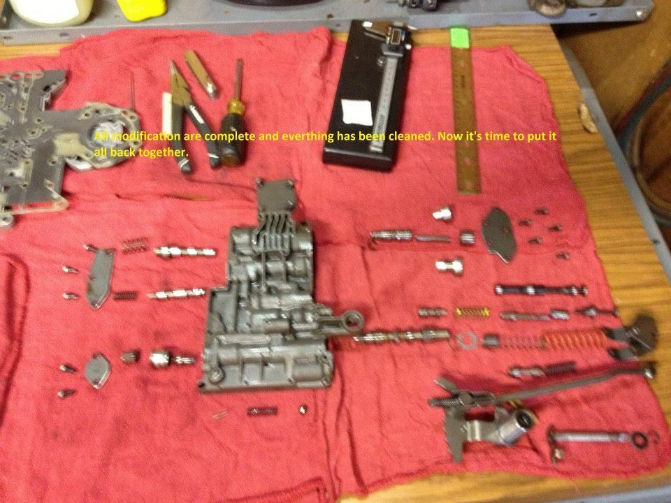
Now I’m ready to button it up after that last hit with the Parts cleaner and compressed air.

1000954_510485619033817_457960842_n_zpsrwf02rg6.jpg


All done and tucked away

1238002_510485639033815_910519358_n_zpsc6j19txh.jpg


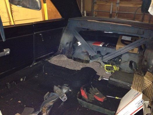
All buttoned up and ready to go on the shelf. Problem is I'm all out of space in my little one car garage. lol


First A727 rebuild is in the books!
Whew! this is addictive for sure. :D

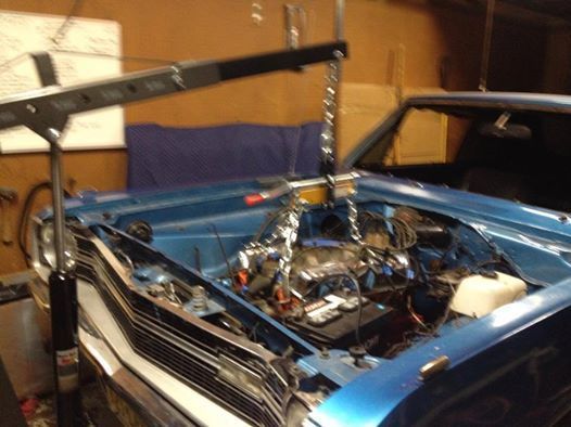
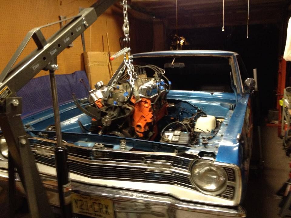
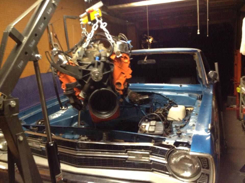
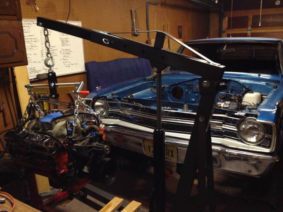
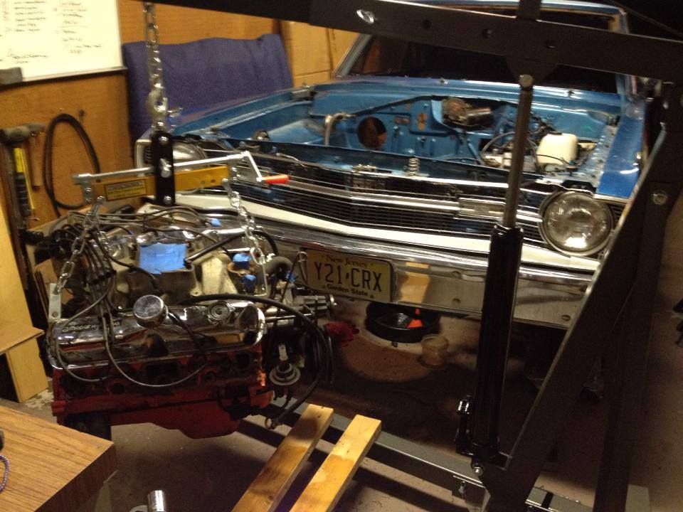
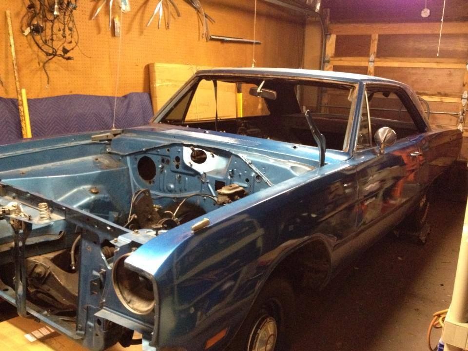
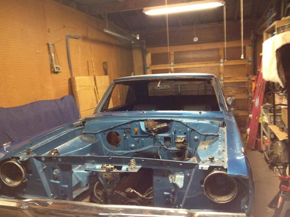
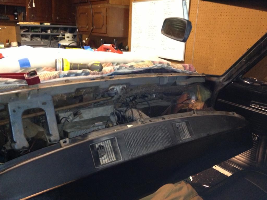
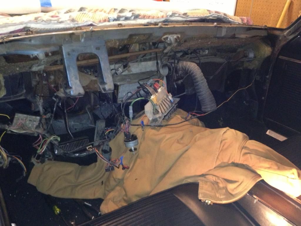
It's time to make some room in the garage to pull the engine out.
 
The '69 ignition switch bezel is plastic. Behind the dash is a metal bracket spot welded to the dash frame to hold the ignition switch and bezel in place.

Also pic of '69 shifter. I would imagine you could just change the knob.


Thanks for the pictures... I've got to figure out the ignition for sure. Does yours have the long switch or the short? I think 69's had the longer one and you're spot on the one in my dash is the shorter style.
 
As I write these posts (and review them) I can hardly believe how much the project has changed and grown from what I thought it would be when I started it. Backing into this thread made me realize how far the project has come and yet there is so much left to do.

Now that I've gotten this thread up to speed ... from here on things will slow down because the work is going to be happen real time.

My garage is getting tight making work space a premium making engine removal interesting. Here are a few pictures of the 318 engine and 727 pulled out in close quarters. lol
I separated the trans first and left it under the car so I could remove the 318.

960172_518022811613431_1171998866_n_zpse9hecd4x.jpg


1379847_518022834946762_1096800882_n_zpsn2im1ju2.jpg


1233380_518022864946759_1660011635_n_zpshegx2gbw.jpg


1384102_518022954946750_1116563535_n_zpsozxsicbk.jpg


734120_518022888280090_1951996579_n_zpszwmnzvfh.jpg


1382870_518842244864821_1948524040_n_zpszozdquyw.jpg


Check out the custom work the previous owner did on the K frame to accommodate the power steering lines. Aye!

1235311_514213738661005_1354838677_n_zpsf0zkvgc1.jpg


A friend has offered to loan me his welder. I haven't done any welding before so I'm excited to give it a try. I don't have High expectations.
 
Chip away at the stone... Singing a little Areosmith circa 88' because it feels right. lol

Not much left.... Show no mercy. :D

1391864_530467500368962_1630550556_n_zps7srfsyrt.jpg


dartbay_zps04326e84.jpg


We'll see what surprises lay beneath.


1378711_529611917121187_175937267_n_zpsaefgyipe.jpg


Original door cards Sept 6 68

1378754_530262140389498_190236269_n_zpsorsgxqvb.jpg


1385024_530262180389494_184006358_n_zpszmbbikki.jpg


1377192_530262153722830_373716895_n_zpsxahdznzk.jpg


The wall of wire and trim.

1382994_530467343702311_336893962_n_zps1zratb1b.jpg


This is the rough side

1380189_530484847033894_1619837940_n_zpsc9omo1aj.jpg


IMG_4987_zps9b6d9153.jpg


I haven't found the build sheet yet. I'm guessing my chances of finding it are slim to none.
 
I haven't had much time... the last few days have been hectic.

I was able to find some space to store my seats which really helps with the space constraints in my garage. As a bonus i've made arrangements to store the 340 until I need to put it back in the car. They are little things that really help.

I know I haven't said much about the 340 so here is a teaser. I'll write more about it after I get the body out

This is what it looked like when I hauled it home

DSC03602-1_zps747f37f4.jpeg


The 340 rising out if the ashes.
Here's a pic of the long block.
Ready for some MOPAR red. (You can see the X heads in this pic)

1385549_530598763689169_2067268683_n.jpg


Stay tuned. :burnout:
 
I am absolutely fascinated with this thread and read each part 2 to 3 times. I really look forward to reading each step. I am not computer literate so showing pics of mine does not seem possible lol.
 
-
Back
Top