charging issues

-
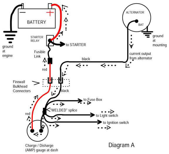
Bypass your bulkhead connector.
Do it before your car burns down.

Run a heavy gauge wire with appropriate sized fusible link from the alternator output stud directly to Bat (+) stud on starter relay.

See if this fixes it. I personally would do this to every single Mopar on the road. EVERY ONE. I almost lost my Dart TWICE to this issue, I got tired or replacing harness's constantly. The ammeter won't be accurate but honestly, I have more faith in the entire rest of the system than the ammeter. I actually bypassed my ammeter at this point because it left me walking once and it wasn't accurate anyway.

It's funny, once I took the ammeter and bulkhead out of the circuit, I stopped roasting regulators, alternators, and batteries.
 
Dammit, beat me to it while I was typing.

The bulkhead connector solved ALL my gremlins.
 
just so i understand... is the amm gauge a positive and a negative? or is it positive current flow through the gauge ? AND where exactly do the wires originate from to the gauge? i am going to do this FOR SURE because i cant afford to fry the harness, but i need to know where the wires lead to, and THANKS A MILLION
 
just so i understand... is the amm gauge a positive and a negative? or is it positive current flow through the gauge ? AND where exactly do the wires originate from to the gauge? i am going to do this FOR SURE because i cant afford to fry the harness, but i need to know where the wires lead to, and THANKS A MILLION

Download a shop manual on this thread......


http://www.forabodiesonly.com/mopar/showthread.php?t=132309&highlight=manual,+download

Usable diagrams from here:

Go down to wiring/ electrical and select your model/ year

http://www.mymopar.com/index.php?pid=31

and MOST important, READ THIS ARTICLE

http://www.madelectrical.com/electricaltech/amp-gauges.shtml
which came from this web page

http://www.madelectrical.com/

This diagram came from that article, and shows a simplified current path of the big current conductors through the bulkhead. What is NOT shown here is the bulkhead connector for the "dark blue" IGN run wire

One thing I forgot to point out, and this diagram shows, is that you can have MULIPLE problems, IE three or four bad connections in the bulkhead connector, AND the "WELDED SPLICE". One of our members I was conferring with just found a bad one, and that makes some 6 or so bad splices in my lifetime. This is a factory welded splice in the under-dash harness, all taped up.

amp-ga18.jpg
 
the battery is good and charged at 12.05v .the blue field to battery + is .5v , clearly a cause for concern as you posted .2v is acceptable but anything over that is a problem. i have never ran these tests before and i am new to this testing, as i have always just replaced parts without any problems. i have no clue what could cause this. thanks again....
 
the battery is good and charged at 12.05v .the blue field to battery + is .5v , clearly a cause for concern as you posted .2v is acceptable but anything over that is a problem. i have never ran these tests before and i am new to this testing, as i have always just replaced parts without any problems. i have no clue what could cause this. thanks again....

To reiterate some of the PM, start by looking at the Madd simplified diagram above. Some of the bad points could be

The big red and big black going through the bulkhead

Bad connections at the ammeter or ammeter itself

Where the arrow shows from the welded splice to the ignition switch, the switch connector, or the switch itself, or the dark blue coming off the switch from the connector, and the dark blue then going back out through the bulkhead

AND the welded splice, rare, but happens. One member found a bad splice just some time ago.


ONE thing that can sometimes help is to use a "heavy load" to load down a suspect circuit. Use oldheadlights, stop / tail lights, etc. For one thing as you are looking, you can wiggle wires and connectors, and LOOK at your "test load" to see if it dims!!!

So an example would be to hook a headlight from the battery ground to the dark blue IGN buss and set up a meter across it where you can see the meter. Then go around and feel for head in the harness and connectors, and wiggle the harness and connectors, look for changes on the meter or lamp brightness.

You need to scare up some lengths of no14 or so wire, and some decent quality alligator clips (used to be Belden, NAPA) and make some clip leads. Radio shack sells clip leads, but for these kinds of tests, they are marginal.

Stay with it!!!!
 
If your 73 has a electric choke assist , it's controller is mounted with one of the coil bracket bolts. Disconnect that things power supply. They can short out internally and cause all sorts of issues. It's not absolutely required and probably doesn't function properly today anyway.
While in that area, seperate the off white rectangular harness connector the factroy added there. Your alternator and other wires pass through that connector.i've seen meltdowns in that one too.
There is also a few harness connectosr behind the left kick panel . I've seen one of those melted too. A little moisture and subsiquent corosion over 40+ years can reek havok on electrical.
 
ok i will keep at it. so far, i have a new starter relay = bat + fusible link directly to the black wire side of the gauge. the gauge has been deleted. from the black wire side where it WAS at the bulkhead, directly back to the relay. then a direct connection from the alternator to the + side on the relay. now i have no gauge to tell what it is doing, and im afraid of cooking something, if the short is in the ignition switch or the ignition wire itself. this sucks. an FYI ; the bulkhead connections looked real good, and i havent run across any melted wires, and the gauge and wiring all looked good. i havent been able to locate the welded splice , i have the cluster completely out. if this is in the ignition switch itself, or the wiring , i may have some real trouble finding that out. but thanks guys .i am going to button up what i have so far and hopefully it doesnt burn down lol
 
after that wiring, i have not started the car.with the key in the run position, i now have .3v from the blue field wire to the + on the battery.at least it is .2v less than it was, and now i am lost on what to do next.
 
If you have a load on that wire, IE the ignition system and regulator/ field, .3 is livable FOR THE MOMENT. I'd leave that part for now, and move on, come back to it later.
 
with it running, i have .003 from the - batt to the regulator case. so my grounds are GOOD.i have 14.4-5 v across the batt running.
 
so at this point, can i rule out the battery, alt and regulator? is the voltage across the battery ultimately what the gauge reads? is there somewhere i can read the total voltage into the system with my meter ,because i dont have a gauge now and i dont have access to one.
 
i put my original alt and VR back on.i have .24 v from the blue field to the + battery. i have 13.6 v across the battery while running, and i have .000 from the negative to VR case.
 
YOU ARE THERE. 13.6 is a tiny TINY bit low, but I suspect the regulator is cold Have you got or downloaded a shop manual? The typical voltages VS temperature are in there

If you don't have and don't want to buy a voltmeter just now, you could wire up a couple of leads to plug your meter into, and just throw it on the seat.
 
13.6v is a whole VOLT too low for a cold battery. Go back to whatever combination gave you 14.5v

Earlier you said your battery was "good & charged at 12.05v" Nope.

12.05 is closer to dead than fully charged. 12.6+ is fully charged. I have a battery here on the bench I use for testing. It has not been charged for at least a week, and it measures 12.65v

If you have a battery charger, overnight charge the battery & check again.

.
 
the 13.6 is actually up now to around 13.8 or so across the battery while running. i checked all voltage in and out of the steering column and not one wire read under or over 13.6-8 v while running. the battery sits at 12.3 v with the car off. i have around 14.4 coming off of the alt + stud to ground. i have not felt any warm wires and it seems as though the signals are working better. i really need to get a volt gauge because im not really sure exactly what it is charging at.
 
switching my voltage regulator was directly responsible for the 1v drop at the battery. its an older mopar electronic and i thought it was still good. heres the deal : my original VR shows 13.8v across the bat and .24v across the blue wire alt field and the +bat. the new one shows 14.5 at the bat and .38 from the field to the bat. weird huh? maybe i should get another VR? any thoughts ? since i have been running it, which hasnt been very long , the voltage in the battery has been climbing.it was 12.05 this morning and right now it is at 12.39. i hope that is a good thing.
 
If the battery voltage is still increasing, it indicates a less than fully charged battery.

You really should check charging voltages on alternators at 1500 engine rpm or so. Most alternators reach full output around 6,000 rpm shaft, and the curve from 2k to 6k is fairly steep.

Run the engine speed up for a few minutes, and check the battery voltage at the posts while the speed is still up.

.
 
i am going to get a volt gauge today. with my wiring is currently done like the below diagram, can i just install the gauge, in the system,where the old gauge was, or do i have to run the system with the alternator power wire back into the mix? thanks again guys,you have been a tremendous help.
 

Attachments

  • amp-ga27.jpg
    51.2 KB · Views: 737
OK, the bypass. It is not just enough to bypass the circuit in the engine bay like the article shows. ON my 67, with the ammeter removed, the alternator charge wire goes directly from the alternator stud to the starter relay stud, no8 or no6 wire

But you STILL HAVE to have wiring to feed power into the car. With the ammeter bypassed, the red and black ammeter wires NOW WORK IN PARALLEL as one wire to feed power into the car.

So you need to connect the ammeter terminals together, either solder, butt splice, or bolt and nut and tape them.

BUT LAST you still need to get the terminals for those two wires where they go through the bulkhead in good shape, either clean or replace the connectors, or run new wires, or splice sections to the old and run them straight through the bulkhead connector

So far as the new voltmeter, it goes to a good ground and "switched ignition" so you'll have to get under the dash/ ignition switch and either hook it to the dark blue IGN feed (put a small fuse inline) or find a good place from the fusebox accessory stuff, like heater or radio circuit.

Basically, you only want the meter on with the key. It does put a small drain on the system, and in a month or so of storage, would run the battery down.

There's a thread on here about doing voltmeter conversions. On my 67, example, you can buy a cheap Sunpro 12V voltmeter, tear apart the ammeter, and mount the ammeter face on the voltmeter. The voltmeter has a "trim pot" (calibration pot) inside, and on mine, I set the pot so that the needle reads 14V when the meter is in the center. So when the system is running normal charging voltage, the old ammeter scale is "centered" just like it's supposed to be

similar to this thread:

http://www.forabodiesonly.com/mopar/showthread.php?t=119480&page=3

more ideas on the subject

http://www.classicmoparforum.com/replacing-ammeter-with-voltmeter-pictures-inside/

http://www.forabodiesonly.com/mopar/showthread.php?t=119480&highlight=ammeter+conversion

http://www.forabodiesonly.com/mopar/showthread.php?t=86773

http://www.redlinegaugeworks.com/
 
cool, thank you again. i have all new direct wiring from the relay going in,and into the cabin power and back out to the relay on a fusible link, and a new 12g from the alt+ to the relay, i hope this cures my charging issue.
 
everything is working great, i have a steady 14v at the new volt gauge, the best part is that it does not fluctuate, and my heater and signals/lights work better than they ever have. thanks again for the help!
 
-
Back
Top