You are using an out of date browser. It may not display this or other websites correctly.
You should upgrade or use an alternative browser.
You should upgrade or use an alternative browser.
Rapom's Rocket - just another Duster build thread
- Thread starter rapom65
- Start date
-
Looking good!
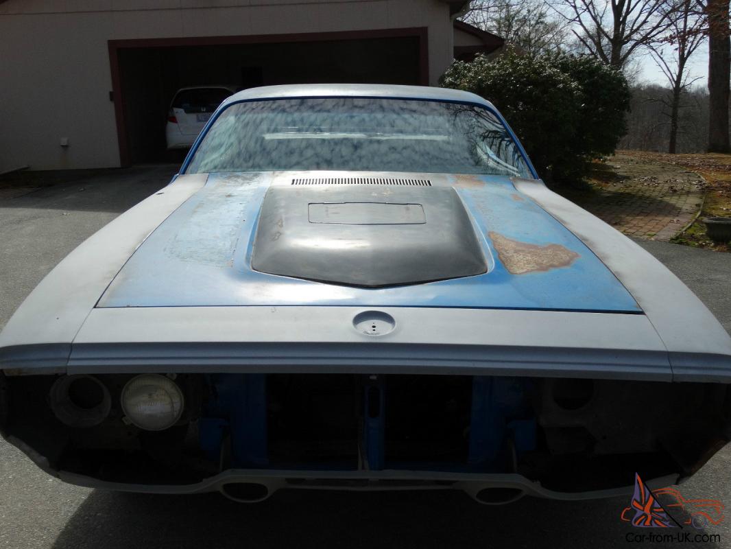
I have to say I'm not a huge fan of the cowl induction scoops, although I'm not as opposed as some. I'm still curious what the 71/72 B body air grabber hood bubble would look like on a '73+ Duster hood. Seems like a similar shape up front as the later duster hood. But they're quite a bit more expensive than the cowl induction scoops are. I'd try it myself, but I'm going to have a '71 Dart front end on mine soon enough.
I have to say I'm not a huge fan of the cowl induction scoops, although I'm not as opposed as some. I'm still curious what the 71/72 B body air grabber hood bubble would look like on a '73+ Duster hood. Seems like a similar shape up front as the later duster hood. But they're quite a bit more expensive than the cowl induction scoops are. I'd try it myself, but I'm going to have a '71 Dart front end on mine soon enough.
rapom65
Well-Known Member
That bulge scoop looks a tad wider than 28" at the front which is what the Duster hood's "rise" is which also gets progressively wider and shallower the farther back on the hood you go. The angles on the leading edge look very similar to my cowl scoop which are off an inch or two from the Dusters flatter angle. Definitely has potential and I wish I had included it in my research before purchasing my current scoop. Of course an original Mopar scoop assy would probably cost the equivalent of a small yacht. I'll have to make that cowl scoop look good and be functional at the same time or it will go bye bye.
rapom65
Well-Known Member
Progress report: decided to tackle the trans mount for the hyd clutch slave cylinder. Unbagged the Lakewood bell housing and the OD trans, God I forgot how heavy that trans is!, and set it on top of my nut and bolt box so I could sit on my *** to work on it. Bolted on the bell housing and the speedo sender (that thang with the red cap converts the mechanical speedo drive into an electrical signal for my Autometer speedometer) then proceeded to take inventory of my scrap bins to see what was available in order to design a mount. Having gone through and rejected about 7 different ideas I found a pair of upper shock brackets that came with my coil overs that I didn't use in the rear suspension fab. One of these looked like it would make a simplistic yet sturdy mount.
Pic 1: Mock up - using the existing hole in the top of the shock bracket I mounted it to the trans support assy using the driver's side outside mounting bolt. This location required the hyd cylinder to be mounted offset from the shock bracket in order to keep the cylinder roughly parallel to the drive train. You can see there is a bushing between the bolt and the shock bracket because the holes were way bigger than the bolt size needed for the heim bearing on the slave cylinder. Problem was the bushing OD wasn't quite big enough and it wasn't long enough.
Pic 2: Finish - After digging through all my hardware I came up with a steel tube that fit the diameter of the shock bracket hole but not small enough for the bolt and a bushings that fit the bolt but not the bracket. With a little massaging the two were pressed together into one bushing and trimmed to the appropriate length. I tacked welded the bushing and a washer nut to the shock bracket and with a squirt of black paint it was done.
Pic 3: Ahh yesssss, progress.
Whats left? Cutting the All Thread to length, adjusting the clutch, routing and making a hyd hose and connecting the wiring to the speedo. Guess I better not celebrate too much yet.
Attachments
That bulge scoop looks a tad wider than 28" at the front which is what the Duster hood's "rise" is which also gets progressively wider and shallower the farther back on the hood you go. The angles on the leading edge look very similar to my cowl scoop which are off an inch or two from the Dusters flatter angle. Definitely has potential and I wish I had included it in my research before purchasing my current scoop. Of course an original Mopar scoop assy would probably cost the equivalent of a small yacht. I'll have to make that cowl scoop look good and be functional at the same time or it will go bye bye.
I took some measurements of the "rise" on my '74 Duster and the "indent" on hood of my '71 Satellite Sebring Plus. Seems to me like someone re-used the measurements from the SSP when they did the Duster, because they're almost identical. The raised section on the '73+ Dusters is 25" from corner to corner on the nose, 29" wide at the end of the hood, and 45" from the cowl to the "nose" of the rise. The indented section on the Satellite/Roadrunner hood is 24.25" from corner to corner on the nose, 29" wide just before the hood vent, and 45" from the "nose" to just in front of the hood vents.
The only thing you'd have to deal with is the diminishing height of the air grabber bulge, because I think the Satellite/Roadrunner hood has a little more curve to it over the length of the hood. Other than that, it seems like it would be almost perfect.
Too bad that even the reproduction air-grabber bubble's are so much money. If it weren't almost 500 bones, I might have to get one to see how it would work. If I were more sold on how they looked on the Satellite I'd buy one and check it, but I kinda like the hood on the satellite the way it is...
[ame="http://www.ebay.com/itm/1971-1972-PLYMOUTH-ROADRUNNER-AIR-GRABBER-HOOD-BUBBLE-AND-DOOR-/321444543457?pt=Motors_Car_Truck_Parts_Accessories&hash=item4ad7967be1&vxp=mtr"]http://www.ebay.com/itm/1971-1972-PLYMOUTH-ROADRUNNER-AIR-GRABBER-HOOD-BUBBLE-AND-DOOR-/321444543457?pt=Motors_Car_Truck_Parts_Accessories&hash=item4ad7967be1&vxp=mtr[/ame]
rapom65
Well-Known Member
Don't ask me how I came up with 28" when I wrote that post. My cowl scoop is 24" at the nose and it is just undersized to the Dusters rise.
That air grabber has possibilities yet. I agree on the issue being the curve of the hood and the diminishing height at the rear. I've found the Duster hood has a curvature to it too. Nothing to dramatic but getting the flat bottom of the scoop to conform to it will demand care is exercised when they are joined. That is why I insisted on a steel scoop as I want to weld the two together not bond it or rivet/bolt it down.
That air grabber has possibilities yet. I agree on the issue being the curve of the hood and the diminishing height at the rear. I've found the Duster hood has a curvature to it too. Nothing to dramatic but getting the flat bottom of the scoop to conform to it will demand care is exercised when they are joined. That is why I insisted on a steel scoop as I want to weld the two together not bond it or rivet/bolt it down.
rapom65
Well-Known Member
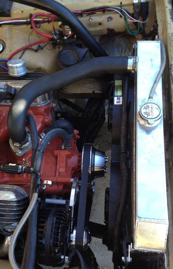
Progress report: Wiring is now complete from the altenator to the Ford starter and continuous duty relays in the back seat. All that's left is routing to the battery and the cutoff switch and their hookups. I know more boring electrical work. Not much visually exciting here but every wire done represents hours and hours of routing, cutting, soldering, heat shrinking and last but not least - thought. Since these photos were taken I rerouted the black 4 ga. cable on the left to follow the other cables on that side.
A new Voltage Regulator, purchased at MATS a few years ago, is also adorning the passenger's inner fender.
A new Voltage Regulator, purchased at MATS a few years ago, is also adorning the passenger's inner fender.
Attachments
Progress report: Wiring is now complete from the altenator to the Ford starter and continuous duty relays in the back seat. All that's left is routing to the battery and the cutoff switch and their hookups. I know more boring electrical work. Not much visually exciting here but every wire done represents hours and hours of routing, cutting, soldering, heat shrinking and last but not least - thought. Since these photos were taken I rerouted the black 4 ga. cable on the left to follow the other cables on that side.
A new Voltage Regulator, purchased at MATS a few years ago, is also adorning the passenger's inner fender.
I totally hear you on the wiring thing. Boring as heck, doesn't look cool, just has to be done. Not my favorite.
I kept my CDR right next to the stock starter relay, you can kind of see it behind the J bar here. Makes it easy to pull power off of the CDR for all the underhood stuff, like the relays for my fans in this picture. Eventually I need to do the bypass on the stock alt gauge, install a voltmeter, and put in a headlight relay. That should finish all of my electrical housekeeping, although everything is currently working through the stock alt gauge.
rapom65
Well-Known Member
Deleting the ammeter would be the next mod I would do on your car before anything else. It's an antiquated system. I'm liking the pully/belt/black alt. your displaying there.
Thanks! It's a 100amp Tuff Stuff alternator, they sell them with a really nice black finish. The pulley's are a March serpentine set up, got tired of tossing the v-belt everytime I revved the engine. Just couldn't get it aligned right to keep it from getting tossed.
Yeah I have the voltmeter already, I just have to disassemble it and put the guts in my alt gauge. Just been busy with other stuff. The wiring on my car is in really good shape, I haven't had any issues with the bulkhead connector so far. It's definitely on my list though.
Yeah I have the voltmeter already, I just have to disassemble it and put the guts in my alt gauge. Just been busy with other stuff. The wiring on my car is in really good shape, I haven't had any issues with the bulkhead connector so far. It's definitely on my list though.
rapom65
Well-Known Member
The stock ammeter, IMO, works fine in a restored application. Put any demands on the electrical system and problems start to arise especially on less cared for OEM wiring because the entire electrical load of the car runs thru that one little gauge. I much prefer a voltmeter which only monitors the system and is not an intragale part of it.
I got pretty lucky with this car, even though the wire wrap was in pretty sad shape the wires themselves, for the most part, are in great condition. Little to no corrosion, burnt, hacked on or otherwise molested connections and the wire is still supple.
I got pretty lucky with this car, even though the wire wrap was in pretty sad shape the wires themselves, for the most part, are in great condition. Little to no corrosion, burnt, hacked on or otherwise molested connections and the wire is still supple.
rapom65
Well-Known Member
Was looking at this thread: Lets see those Dusters ( 1 2 3 4 5) this morning. If your a Duster/Dart/Demon fan you need to check this one out. Not a bad car in the lot. These two cars caught my attention as their stance is just about right. I'm hoping my front rim has a deeper offset to it than the green one's. If that is a Centerline rim then it will.
1 2 3 4 5) this morning. If your a Duster/Dart/Demon fan you need to check this one out. Not a bad car in the lot. These two cars caught my attention as their stance is just about right. I'm hoping my front rim has a deeper offset to it than the green one's. If that is a Centerline rim then it will.Attachments
rapom65
Well-Known Member
The pulley's are a March serpentine set up, got tired of tossing the v-belt everytime I revved the engine.
I don't doubt a serpentine belt system is in my future.
rapom65
Well-Known Member
Not much to report. Work has been initiated on a new mod and I'm documenting it with pics but I probably won't do a write up on it until its close to being done.
New parts have arrived just a day and a half after I ordered from Summit. Moog upper ball joints, poly grease boots for my tie rods and button head LCA bump stops from Energy Suspension.
Also have on the way some new end links for my Hellwig sway bar for a little something I picked up on Moparts "Corners are best" forum.
Sub assemblies are now becoming finished and assembled major components. Feels like I'm starting to make progress once again. This thing might actually get driven some day.
Attachments
rapom65
Well-Known Member
Well my sway bar end links were delivered Thursday.... only not to MY house. Now I've got to fight that battle. Great.
Nothing new to report on the car just random thoughts bouncing around in my brain bucket.
Over the years I've been collecting parts and working on this car I've been raging a debate with myself over sticking with 15" rims and tires vs stepping up to 17,18 or even 19s. I currently have a set of Centerlines that match my narrowed rear axle. I have two sets of old but relatively little used MT "I" Block N50s that you see in a couple pictures. I plan to burn them up during the shake down period prior to paint and body. I'm referring to past that, to when I'll need replacement rubber. The N50 is about an inch narrower and the same height as a 35 series 345-17, so I know what will fit my wheel wells. The 15" performance tire market is almost non existent. The most serious handling tire available in a wide 15 is the Micky Thompson SR. They seem to perform well for the AC Cobra crowd per what I've read. A much lighter car so I don't know how well they would perform for me and my intended usage of the Duster. What they have going for them is a complete set is 1/4, or less, than the custom rear offsets I'd need in a rim & tire package to step up to serious modern technology. The Duster can look good and perform very well with the right newer style rims (72bluNblu's prime example) but the cost is bordering prohibitive. I like the look of a 15, yep "old school", so shoot me. I love the stance of the blue car below, what I'm shooting for, only with wider rubber. The yellow car is set up with MT SRs in 26x10 front, 28x12 rear which would be what I would have to run in these tires. By the time I get this car painted we may be flying around in levitating cars so the whole issue would be mute. Come to the conclusion that to get this answered I'll have to give the SRs a chance and find out what they can do. If disappointed I will have to step up the program. Just hope I win the lottery before then.
View attachment $_20.jpg
View attachment 7896560-cuda-barf001.jpg
View attachment 7896582-cuda-spaz008.jpg
View attachment 7896584-cuda-barf002.jpg
View attachment 7896589-cuda-barf003.jpg
Last edited:
rapom65
Well-Known Member
Decided to show what I've been working on because I wont be able to finish it until the engine/trans/K unit is installed to check for how it all fits together. Started on the hood mods for the cowl scoop. Step one was to get something I could place it on in order to work on it. A friend has had a set of Galvi coated fold up saw horses that I've used in the past and really liked. Set out to find a pair and located them at Home Depot for $17 each. Legs fold up into the cross braces and store easily on a shelf instead of cluttering up needed floor space.
Attachments
rapom65
Well-Known Member
Step two was to lay out where the opening will be cut. Problem with small openings is the engine offset in these cars, aprox 1.5" to the passenger side, which is designed in room for the steering box/column. Hence the need to get the motor in place, bolt on the hood and check for interference. This is what I decided to cut out. After taking out the flange of the bracing I found the top skin and under hood bracing are in contact about 3/4 of the way around. This really helps to simplify construction of the opening.
Attachments
rapom65
Well-Known Member
If you look closely at the corners of the cutout you will see that I took a very small drill bit and perforated them along the cut line. To better show what I'm talking about I crawled under the hood, on that gravel covered ground, so I could get a back lit pic of it. The things I do for you guys!
Attachments
rapom65
Well-Known Member
In progress shot of cutting straight lines with grinder/cutting disk. I sliced up the flange and removed the corners with a couple of wiggles back and forth. The pieces are visible in the lower left corner. Getting the corners cut without bending the hood skin was a bit more involved but a combination of careful grinding and work with a hack saw blade (wrapped with duct tape) had it out in less than a half hour.
Attachments
rapom65
Well-Known Member
rapom65
Well-Known Member
rapom65
Well-Known Member
Tack welded the hood's skin to the under side bracing then traced the outline of the cowl scoop where it will ultimately sit. I've been methodically working some curvature into the cowl scoop also. At this point it's a close enough match to the curveture of the hood to not present any issues when I weld it together. Next step is to make a sheet metal filler strip to close off the scoop ahead of the new opening so the air is channeled to the carb (red lines). I plan to tack weld it to the opening and then seal it to the scoop with a bead of seam sealer so the fit will have to be pretty good.
Attachments
rapom65
Well-Known Member
rapom65
Well-Known Member
rapom65
Well-Known Member
And the final bit of progress for the last few days was routing the charging and supply cables to the cut off switch. Passed the lines through the floor skin into the frame rail, back out the side and then along the inside back to the switch. Used some spare floor plugs as grommets and drilled them to fit snuggly around the cables. Most straight forward way I could come up with to get them from inside the car to the back side of the rear bumper. All that's left is finishing the connections at the cutoff switch and battery + & -. Your up to date.
Attachments
-


