Charging Gremlins

-

iw378

Well-Known Member
Joined
Sep 15, 2013
Messages
794
Reaction score
112
Location
Suisun City, Ca
My new to me 69 barracuda has charging gremlins. I have been reading a ton on here about diagnosing it. Especially 73ABodEE's post from awhile back. Today I plan on doing the splice and reroute and ammeter delete like on madelectrics site. I looked at my firewall connectors last night and they looked bad. Anyways the symptoms I have now are at an idle I'm getting 13 volts at the battery. If I increase the rpm's the it creeps up slowly to about 14.8 or 14.9.
The car has an old school electronic ignition on it and an aftermarket alt. brand new interstate battery. I had the alternator checked and even swapped it out and tried another. I hear you guys talk about a blue field wire and a green field wire. My alt has a green and a red. The red wire was obviously installed at some point along the cars life, and it goes directly to ground on the head.
snpa.jpg

Is this correct ?
As far as getting the fusuble links go on the mad reroute, do they have to be fusible links or just the right size wire ??
Thanks
Luke
 
In addition to what you've found and the mad thing, the original green goes to the regulator, and it appears you probably now have the 70/ later electronic regulator adapted.

The difference in your old system and this one is:

Originally the regulator FED power to the field which was grounded at one end

The 70/ newer system feeds power to the field, power goes through the field, "out" the green and back to the regulator which "controls the ground" so to speak.

So your red wire should replace the blue, and should be "switched ignition"

This may be part of the problem with your overcharging, called voltage drop

What happens is that the path between the battery and the regulator has some voltage drop, and this causes the regulator to "think" that battery voltage is low, thus ramping up charge voltage.

In other words if you were to check system voltage from the regulator ground flange to the ballast resistor (switch side) you will probably find that (warm) charging voltage is right at 13.8, or 13.5--14.2
 
I've been tryin to figure this out on my 74 sort. Charging system is all original, and it overcharges it bad. Had it melt the power wire and stud right of the alternator at one point
 
it appears to have the original regulator in it ?

Check whether the red wire is ground, or goes to switched 12V

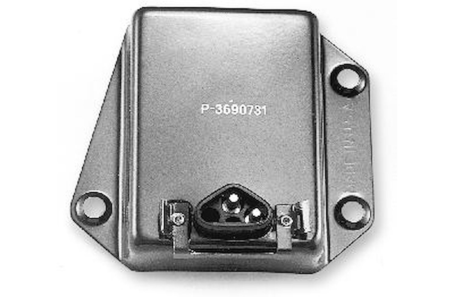
New style:

If you have this regulator, the blue/ tracer goes to switched ignition (would be your red)

Dual_Field_Alternator_Wiring.jpg


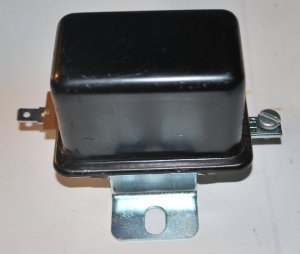
Old style:

In this case the original alternator has one field terminal, the other is grounded right at the brush mount. Someone may have installed a later alternator, and the red wire may be grounding the second field terminal

pic1.gif


New style regulator:

312-P3690731.jpg


'69 and earlier style

4fb959dc6e5e1_95731n.jpg
 
it appears that it is set up like your second picture. What the heck do I do now ?
The red wire on the back of my alt in pic one goes to ground and I guess the green one goes to the field on my regulator.
 
By the way this car looks like it has been set up this way for a long time.
LOL
 
There is no reason that setup cannot work properly. Did you confirm the red is grounded?

First thing to do is turn the key to run, with engine off. Check voltage between the regulator IGN terminal (the top screw terminal in your photo) form there to battery positive.

If you read more than .3V (three tenths of one volt) you have a voltage drop problem

This is the path from

battery -- fuse link -- through the bulkhead -- through the ammeter -- through the ignition switch -- back out the bulkead -- and to the regulator.

So a bad connection in the bulkhead (twice!!) in the switch connector or in the switch itself could be dropping the voltage to the regulator.

One way to "cure" it is to install a relay out in the engine bay, fired by the blue igntion wire coming out of the bulkhead, and use the relay to switch power to ignition and regulator

=============

A second possibility is the regulator ground. With engine running at fast idle, stab one meter probe right on the battery negative terminal. Stab the other onto the regulator mounting flange. Once again, if you read more than .3V improve the ground situation between battery, engine, and body.
 
Yes the red wire on the back of the alt is going directly to ground (bolted to head). I am bypassing a couple of the bulkhead connections now. I'll report back after I do the check you said to do. Thanks a bunch for your help.
Luke
 
By the way, there's not a thing wrong with what was done there. The newer "squareback" alternators have better low RPM charge output. You can, if later you want to, add one wire and go to the 70' / later regulator

But most of the 69/ earlier regulators you buy nowadays are already "solid state."
 
just fired it up. Not good. I did the ammeter bypass, bypassed the batt lead, the blue ignition wire and the alt lead at the bulkehead all with soldered crimps.
Set the voltmeter to low setting and it id .8 at the field wire. started it up and getting 15 v across the batt. I did everything correct. ?????
 
Here's how the voltage drop problem works.

The battery "wants" 13.8--14.2 running, charging voltage. When you have a voltage drop problem, the juice goes through the path I described and in your case .8V. This means that what the regulator "sees" is .8v (nearly one whole volt!!!!) lower than the battery.

Let's assume that the regulator is at 14.2V. That is, if there was no voltage drop, the battery would be 14.2. But there IS voltage drop, .8V!!! So this .8V is added to our assumed regulator set point of 14.2, and.........................15V at the battery!!!!

You either need to find and fix the drop, or as I said, you can add a relay to operate underhood loads.

Now the ground is important, too. Let's say there's .4V loss in the ground. Now instead of having a .8V drop, you have the .8 in the harness, the .4 in the ground, for a grand total of 1.1 volt!!!
 
So with my electronic ignition you feel that I do not need 2 fields ?
I have no Idea where my voltage drop would be at. I eliminated the ammeter and crimped and soldered the black alt wire, red batt wire. and blue ignition wire.bypassing the bulked connectors. when I checked for voltage drop on grounds I had the car running, meter going from batt neg to the mounting tab of regulator and was coming up with .01.
Just for the hell of it I disconnected the red ground wire on the field connection at the alt and it would not put out any charge.
How do I check the output volts at the alt ?
Luke
 
Voltage at the alternator output studis not all that important, except that with the original wiring (before the bypass) you could have an additional problem, IE bad connections in the charge wire (bulkhead) and at the ammeter, could cause a condition where the voltage at the battery is a little high, but somewhat normal, while the junction INSIDE the car feeding the ignition switch and fuse panel is quite high. By doing the ammeter bypass you have helped "cure" that possibility

The voltage (charging) at the alternator should be "close" to same as battery, but if it's a volt high, no big deal. This will change with charging current, and with the size of wire and length used going to the battery.

This whole thing comes down to the path I described earlier. Get your brain in gear and think about this. Refer to a diagram and follow along. Here's where the voltage drop HAPPENS

The voltage "comes" from the battery. It goes through the fuse link-----so far so good

Now it goes through the bulkhead connector. BINGO One connection that could be bad.

Next goes to and through the ammeter. TWO MORE connections including the ammeter itself.

Next we come out of the ammeter (on the black wire) and to the factory "welded splice." It's rare, but this splice can and HAS failed. More opportunity for a voltage drop.

Next place we go is the connector going "into" the ignition switch. BIG suspicion here.

Through the switch. Hey, guess what, you think maybe 30-40 years has worn out that switch?

Out of the switch, and out the switch connector on the dark blue "ignition run" wire ONE MORE place for a poor connection.

Last, out the bulkhead connector we come AGAIN on the "dark blue" "ignition run" wire.

Every single place this "voltage" travels is a place(s) where you can suffer drop.

There's only two ways to fix it...........................

1--Chase down and check voltage at every single point, and fix every single problem

2--Install a relay under the hood and let the original "run" wire fire the relay, then use the relay to key all the underhood loads.
First off, Thank you for your time and patience. I greatly appreciate it.
As for the list of things to check we have whittled it down.
Fuse link still have to check but brand new today.
Bulkhead connector gone.
Ammeter in gone, ammeter gone ammeter out gone. Spliced with crimp and soldered connection.
Welded splice. Will check tommorow. If it's bad Resolder ??
Next the ignition switch. how can I check that ??
So you still think I can get this to work right with the old school regulator and one of the fields going to ground.
 
The regulator MAY be bad, but you won't know until you get rid of the voltage drop. Now you CAN test for that, too.

"Rig" yourself a temporary wire out of no14 or so, connect to the IGN terminal of the regulator, and the big battery stud on the starter relay. In other words, you are now temporarily powering the regulator direct from the battery with a short, large wire and good connections.

Warm the engine (regulators are temp sensitive) and check running /charging voltage as you did before.

Don't leave the temp connection hooked up with engine off, because you'll be powering both ignition and regulator

Checking for drop in the rest of the circuit same way is you initially did it:

Key on, engine off, one meter probe clipped to the battery (or battery stud on the starter relay) and see where the drop is coming from. Visualize in your mind the circuit path, -------

Check at the interior side of the bulkhead connector on the dark blue "run" wire, move from there to the "in" and "out" terminal of the ignition switch.

You will soon see where the problem lies.
Trying to wrap my head around this. For the voltage drop test we first check at the green field wire to get the whole circuit voltage drop. to eliminate voltage drop we check each connection along the way. ?
On a side note If I disconnect the red wire that's grounded off the field terminal on the alt total voltage drop is .3 but is Not charging, when it's connected it is .7 and charging, while I check the grounds while running batt neg to reg mounting tab I have .2 so my grounds are good.
Thanks for helping me out.
Luke
 
No not at the green, you have to re-read what I posted and follow it closely

Disconnecting the red is simply leading you off on a wild goose chase. You are quite simply breaking the field circuit, and causing it not to charge.

Re--read the part about the circuit path, and follow along on a circuit diagram. Voltage drop works like this:

You start at a battery, and every single wire, switch, connection, terminal, can have a small amount of RESISTANCE. This resistance is ADDITIVE. That is, if there's a tiny loss in the ignition switch itself, you may lose a few tenths of a volt right inside the switch. Maybe one or both of the connectors on the switch loses a few tenths. Add that in. By the time you are done with the circuit path, you add everything up to the .8V you are losing now. This circuit path starts at the battery, and ends at the regulator IGN terminal NOT the green field wire.
 
A voltage regulator drives the field current to regulate the voltage at the IGN terminal (blue wire) of the regulator. If you measure the voltage at the IGN terminal it should be about 14V. If the battery measures 15V, then there is a 1V drop. If the IGN is at 15V, then the regulator is at fault. I do not think you have shown us what the IGN terminal measures.
 
Thanks for the replies fellas. I'll report back tomorrow. On my regulator the bottom tab is the IGN tab. This is wearing me out but it will get done.
 
Thanks for the replies fellas. I'll report back tomorrow. On my regulator the bottom tab is the IGN tab. This is wearing me out but it will get done.

I may have steered you wrong there. I was thinking the screw terminal, you are correct. "Push on" is ignition
 
No Worries I just appreciate the help. I'll dig into it again tomorrow morning.
So I'll just pull of the blue wire at the reg and stick the probe in it. I did check the ignition switch , I checked the Blue wire at the back of the ignition switch with the switch on run and the positive probe of the voltmeter on the battery positive and got .2
 
No don't disconnect. You need to figure out a way to probe it with everything all hooked up "as per normal." This is because voltage drop depends on the current load placed on the circuit.
 
I think you can remove the mounting screws, rotate the regulator so the IGN , is on top, replace the screws. Stick a small wire in the connector, or slide it back enough to make measurement. Be careful not to short to case ground! The same point is also available at high side of ballast resistor, not the end that goes to coil.
 
-
Back
Top