the title says it even though it sounds stupid. im getting confused on what should be a simple system. anyway here goes and any help is greatly appreciated. was out driving the car the other day and noticed that the amp gauge was showing a slight discharge, it usually reads a slight charge or not at all depending on its mood I reckon. anyway I stopped and went into a store and came out and restarted, it started fine but showed even further discharge. I had to make another stop and when I was ready to go home it was close to dark, had to turn on the headlights, with the headlights on it showed a serious discharge but all the lights were nice and bright and it started up with no problem so I headed home, drove probably less than a mile and the car just shut down, lost all electrical, lights ign everything. had to have it dragged home and stuck it in the garage. started cking it this morning and found that one of the previous owners had installed a "fuse" holder in the red wire coming from the starter relay to the amp gauge, i'm assuming in place of the fuseable link but its right at the bulkhead connector. it had a 20 amp fuse in it that was blown. replaced the fuse and it fired right up, put a meter on it and its overcharging, fluctuates a little but basically 15.5V with the headlamps on but the amp gauge still shows the serious discharge. idk, I started checking and looking at posts but im getting confused I suppose. I cant seem to locate a service manual with charging system trouble shooting if I could im sure I could get it figured out, anyway here's what ive done. im getting battery voltage to the B terminal on the alt, when its running the voltage at the battery and the B terminal match. I unplugged the green field wire and it quits charging, plugged it back up goes back to 15.5V. I added an extra external ground to the voltage regulator, no help, I put another regulator on it (already had it , should be good but who knows right but what are the odds of them both being bad and doing the same thing) anyway no help, if I unplug the voltage regulator and ck the voltage it shows about a volt less than battery voltage running or not running on both wires, if I backprobe it it shows about a volt less than battery volt on the "I" wire and approx. 6 volts on the "F" wire (idk if that's right or not). i cked the connection at the amp gauge and it was tight, i unhooked those and connected them together with a nut and bolt just to bypass the gauge and still no help. looking at the wiring diagram on a mad link i found it shows the voltage running from the alt on the black wire to the amp gauge and then back to the batt, if i unhook the amp gauge i don't have any voltage on the black wire, only the red wire and if i unhook the black and red wires from each other (the ones that are for the amp gauge) to check for voltage on the black wire with the car running it kills all power and the car dies like it did the other night so that diagram is confusing to me. im sure im overlooking something and ive read so many posts and looked at the wiring diagrams so many times im confusing myself. i also found a simplified picture of the charging circuit and followed all of that out and all seems to be connected correctly. i do loose that volt from battery voltage like i spoke of earlier at the volt gauge and ign switch connector but they are still about 14.5v with the car running so its still seeing the overcharge in there. the bulkhead connector obviously is old and not the greatest but doesn't seem to terrible but is dropping that volt going inside, not sure if that can cause my issue but it is showing overcharge at the amp gauge and ign switch connector but shows discharge on the amp gauge itself when hooked up. so sorry for the ramble, i was trying to give all the info i had. i did stick another alt that i had laying around on it but still no help. any suggestions? anyone have a link to a service manual where i can follow diag? thanks again.
You are using an out of date browser. It may not display this or other websites correctly.
You should upgrade or use an alternative browser.
You should upgrade or use an alternative browser.
discharge/overcharge?
- Thread starter ktcnn94
- Start date
-
TrailBeast
AKA Mopars4us on Youtube
Sounds like you should put a piece of tape over the amp gauge and drive it. 
What does it do if you run about a 10 ga wire from the large stud on the back of the alternator to the positive post on your battery with the car running? (measure voltage at idle and at 1500-2000 rpm)
Besides blowing the fuse your charging system may be doing exactly what they do.
They do have some voltage and amp variations just by design, and 14.5 or so at the high point is fairly normal.
I run a 30 amp auto resetting breaker where you have a 20 amp fuse, and it's possible that the battery needed more than that fuse could handle at the time.
67Dart273
Well-Known Member
............ a slight discharge, it usually reads a slight charge or not at all ................... showed even further discharge. ............ "fuse" holder in the red wire coming from the starter relay to the amp gauge................. it had a 20 amp fuse in it that was blown. replaced the fuse and it fired right up, put a meter on it and its overcharging, fluctuates a little but basically 15.5V with the headlamps on but the amp gauge still shows the serious discharge. i................plugged it back up goes back to 15.5V. I added an extra external ground to the voltage regulator, no help, I put another regulator on it (already had it , should be good .............. wiring diagram on a mad link ............... i unhook the amp gauge i don't have any voltage on the black wire, only the red wire and if i unhook the black and red wires from each other ............... kills all power and the car dies................... i do loose that volt from battery voltage like i spoke of earlier at the volt gauge and ign switch connector but they are still about 14.5v with the car running so its still seeing the overcharge in there. .............
DAMN that is hard to read, LOL
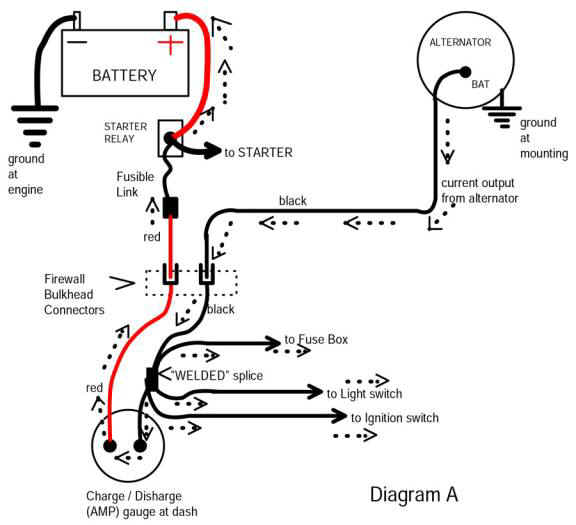
OK please do read the MAD article carefully, as it explains the hows and whys of much of the grief with these systems. The diagram on the MAD site is fairly accurate though simplified
For a shop manual, ...........EASY, and FREE
This thread..........
http://www.forabodiesonly.com/mopar/showthread.php?p=1970088617
and more of them at MyMopar
http://www.mymopar.com/index.php?pid=31
Also at MyMopar are aftermarket, simplified wiring diagrams which are not always accurate but somewhat easier to follow "for some jobs."
http://www.mymopar.com/index.php?pid=24
ALSO bear in mind that for some years the shop manual is WRONG there is a wire (green / red?) and yellow? through the bulkhead connector dealing with the start wire and the horns. There is a mistake in some of the shop manuals
==========================================
NOW that fuse in the red wire is COMPLETELY inadequate. It must be much larger, perhaps 50A or so. I would try to find some "fuse link."
The 14.5.....15.5V is confusing, or maybe you have an intermittent connection that is throwing you off
HERE IS the deal on over voltage
1....Rare but sometimes a bad battery can do this. Charge it up, have it tested if possible.
2....USUALLY this is because of voltage drop in the harness, and sometimes drop in the ground circuit
3....If you fix or check 1, 2 above, it can be a REGULATOR
=================================================
HOW TO check for voltage drop. Easy. Get your meter, and clip the meter to the VR IGN terminal and to battery POSitive post. Turn the key to run, engine off. You should read a VERY low value, the lower the better. More than .2--.3V (3/10 of one volt) means there is excessive drop in the power to the VR
THIS circuit "path" is (on unmodified cars............)
Battery.........starter relay stud.........fuse link.......through bulkhead...(red).......to ammeter.......through ammeter.....out (black wire).........to "welded splice"...........to ignition switch connector..........through switch..........out switch (dark blue)........back out through bulkhead..........to underhood loads, IE ignition system and VOLTAGE REGULATOR
MOST COMMON voltage drop problems..........
Bulkhead connector (large red, large black, and blue IGN)..........ignition switch connector........and the switch
LESS common.........ammeter connections, and ammeter wire terminals....
RARE but has happened...........failed "welded splice". This is a factory welded splice in the BLACK ammeter wire a few inches away, taped up in the instrument panel harness. "Save it for last"
===========================================
Check the GROUND circuit. If the above checks OK or you have fixed it, now check the ground. Start and run the engine at "low cruise" (good fast idle) and make this check first with all loads off, and again with loads "on" ........lights, heater, etc
"Stab" your meter probe directly into the top of the NEG battery post. Stab the remaining probe into the mounting flange of the VR. Stab "hard" through paint, etc.
You should again read almost no voltage, or perfect is ZERO. If you read more than .2V you have a poor ground. VR MUST be grounded to "same as battery" negative.
============================================
If you do the above, and it still runs above 14.2 when warm, replace the VR. Buy a good one.
67Dart273
Well-Known Member
HOW this works............the MAD diagram
http://www.madelectrical.com/electricaltech/amp-gauges.shtml
Bear in mind that I learned "electron flow" current from NEG to POS but often I talk about "the circuit path" and sometimes go from pos to ground. This is simply a way to thing "in circles" and to identify components.
All power for these cars, except the main starter power, goes through the red wire, through the ammeter.
So you main "path" is battery.........starter relay.........fuse link.......(red).......through bulkhead...........ammeter.......through ammeter.........and out on the BLACK........and to the WELDED SPLICE
This splice splits off and feeds (depending on year)
headlights power ONLY (tail and other is fused)
hot buss feeding to the fuse panel
main power going TO the ignition switch
Now the alternator is "coming back" the other way. Alternator output comes through the bulkead (BLACK) to and through the WELDED SPLICE and to the AMMETER, and back through to the battery
This is why when you unhook the ammeter you kill all power.........all the car loads come off that WELDED SPLICE
sorry if it was hard to read i was just trying to get all the info in there i could think of, thanks for the replies, im gonna do that mad upgrade tomorrow, ill go get the necc parts and change all that over, not sure if it will fix the problem but im sure it wont hurt to go ahead and update that stuff anyway.
trailbeast, i didn't try to add that 10gauge jumper, ill give that a try also tomorrow and see what it does, should i leave everything stock hooked up and just jump that over and see what it does, also that 15.5 volts at the battery terminals is at idle without raising the rpm's.
67dart273, info is very helpful, i will try that stuff tomorrow as well, i feel like the ground to the VR is good as i ran a ground to the battery ground to the VR case but i will ohm it out and voltage drop the ckts.
trailbeast, went back out and jumped a 10 gauge wire from the battery to alt battery post and no change. it seems like a voltage regulator problem to me but i don't understand why the amp gauge shows discharge while the system is clearly overcharging 15v at idle with no lights on just now when i checked it before jumping it. is there anyway to test the regulator, i don't mind to buy one at all if i need it, just hate to waste money on it or if something is wrong and messes up a new one too since i have two of them doing the same thing right now.
TrailBeast
AKA Mopars4us on Youtube
sorry if it was hard to read i was just trying to get all the info in there i could think of, thanks for the replies, im gonna do that mad upgrade tomorrow, ill go get the necc parts and change all that over, not sure if it will fix the problem but im sure it wont hurt to go ahead and update that stuff anyway.
trailbeast, i didn't try to add that 10gauge jumper, ill give that a try also tomorrow and see what it does, should i leave everything stock hooked up and just jump that over and see what it does, also that 15.5 volts at the battery terminals is at idle without raising the rpm's.
67dart273, info is very helpful, i will try that stuff tomorrow as well, i feel like the ground to the VR is good as i ran a ground to the battery ground to the VR case but i will ohm it out and voltage drop the ckts.
No problem, and it really doesn't matter that much if you are going to do the Mad bypass anyway.
It would have just given you an indication of what the bypass would do if everything else stayed the same as it is now.
15.5 is a little higher than I would be comfortable with at idle because it'll go higher with rpm's (unless your car idles at 1000 or more already)
Following Del's advice will take some time and patience, but it will also make sure it's right.
He and I have had a disagreement in the past over my using the 30 amp relay where your car had the 20 amp fuse, but my car had a 20 amp fuse there when I got the car and it blew occasionally.
His point was that the fuse or whatever that is used in that circuit should be capable of handling the output that the alternator is capable of (60 amps in my case) but I figured if the 30 amp breaker could handle the normal usage loads then if it tripped it would indicate that there may be a problem somewhere before that full 60 went through the system or to ground.
2 years now and it has never tripped once, even with every electrical device in the car on at the same time.
I do have a lot of LED's in my car though (brake, markers, signals and interior lighting), as well as the headlight relay kit which greatly lessens the amp loads on the cabin wiring and switches.
67Dart273
Well-Known Member
trailbeast, went back out and jumped a 10 gauge wire from the battery to alt battery post and no change. it seems like a voltage regulator problem to me but i don't understand why the amp gauge shows discharge while the system is clearly overcharging 15v at idle with no lights on just now when i checked it before jumping it. is there anyway to test the regulator, i don't mind to buy one at all if i need it, just hate to waste money on it or if something is wrong and messes up a new one too since i have two of them doing the same thing right now.
If you run a large ga. wire direct from alternator to battery.........even temporary..........
And temporarily connect battery direct to VR IGN terminal, and make certain it's grounded, that should produce "about" 14V with battery warm and charged. My personal feeling is no less than 13.5, no more than 14.5, and "optimum" 13.8--14.2
TrailBeast
AKA Mopars4us on Youtube
One thing to note also, is that there is a big difference between volts and amps as to how they show on a gauge.
My Dad always told me I should use amp gauges instead of volt gauges, and my argument was that I didn't care what the draw or state of charge was but more the system total volts available.
Lack of amps is a lot easier to track down (diagnose) usually that a lack of volts.
It always has been for me anyway.
Rustedwrench
Well-Known Member
if I unplug the voltage regulator and ck the voltage it shows about a volt less than battery voltage running or not running on both wires, if I backprobe it it shows about a volt less than battery volt on the "I" wire
If the voltage at the voltage regulator ignition wire is only 14.5 volts when the alternator is putting out 15.5 volts then the regulator thinks the voltage is where is should be. To put it another way, when the engine is started the regulator increases the alternator output until it sees 14.5 volts. It does not see the alternator output is 15.5 volts because it is only seeing the 14.5 volts. You are losing 1 volt somewhere between the battery and the regulator.
Print out a wiring diagram of your car and trace the ignition wire on the regulator with a colored highlighter to see where it goes through the firewall, ignition switch, etc. to find the voltage drop.
Not to give you a hard time but that post is very hard to read. It made my eyes cross and my brain explode. I had to buy a new brain on ebay. Using capital letters, punctuation and paragraphs will make it much easier for people to understand the problem.
67Dart273
Well-Known Member
If the voltage at the voltage regulator ignition wire is only 14.5 volts when the alternator is putting out 15.5 volts then the regulator thinks the voltage is where is should be. are losing 1 volt somewhere between the battery and the regulator.
.
Exactly correct and I've written about this many times. Voltage drop in the harness, from battery to the VR. Bulkhead connector, ignition switch connector, or ignition switch.
Sorry for no caps, anyway I was feeling like the "lost" volt is the issue, I done the "mad" repair to correct any issues with the bulkhead connector. I replaced the red and the black through the bulkhead and also "overlayed" the blue wire from the ignition switch through the bulkhead (just at the bulkhead), but I'm still a volt short at the regulator connector and at the ballast resistor. If I put a jumper from the battery to the "I" terminal it charges correctly. From all of my testing it looks like I may have high resistance in the welded splice, all the wires that come from that seem to be affected and dropping that 1 volt but nothing else.
67Dart273
Well-Known Member
You are getting closer---very close. I would leave the splice "for last." These have and do fail but rare.
MUCH more likely to be the ign switch connector or the switch
Check the voltage at the power going into the key and coming back out on the blue IGN run line.
Did you mention what year? this is? I don't see it
MUCH more likely to be the ign switch connector or the switch
Check the voltage at the power going into the key and coming back out on the blue IGN run line.
Did you mention what year? this is? I don't see it
Sorry for the delay, yeah the splice will be last for sure. I'll try to check it some more this eve and post what I find. I thought I had posted the vehicle year etc but skipped over that, was too distracted with the problem I suppose. It's a '71 swinger v-8 auto.
I got to check it some last nite, the voltage loss wasn't near as bad, its been sitting a couple of days and not ran so heat/running may affect it some. Looks like I've got about .5v drop through the ignition switch. I cant seem to find any literature on how to replace the ignition switch. I've looked at the service manuals online I've found but didn't see any replacement instructions for the switch. Does anyone have a link or instructions for this. I'm sure you probably remove the steering wheel and go down through the top but I'm not sure if it's cut and dry when you get in there or if I'll need any special tools etc. This may or may not be all the problem but there is that .5 drop that may get worse with heat so I'll replace that and then recheck it. Any suggestions on where to get a switch, seems like everything is made in china now so I want to be able to buy a good part. I don't want to pay more for a part thinking its better cause it costs more only to find out it's made in china just like the cheap one. thanks for the help.
67Dart273
Well-Known Member
AbodyJoe had some GREAT photos on the column / switch
http://www.forabodiesonly.com/mopar/showthread.php?t=128836
http://www.forabodiesonly.com/mopar/showthread.php?t=128836
-


