DIY Flywheel / PP / Rotor / Drum Balance Checking Fixture

-

weedburner

Well-Known Member
Joined
Oct 20, 2015
Messages
279
Reaction score
349
Location
Wa State
I made this simple balance checking fixture yesterday, wanted something to quickly verify flywheel and PP balance at home. My first pass at this was just proof of concept using materials I already had on the rack, basically angle iron and some cold rolled shafting. Turned out it works pretty good for what it is, detects an an out of balance 2 grams on a 6" radius. Plan is to use it to verify neutral balance of the flywheel first, then add the pressure plate to further balance the assembly. Here's some pics with an old cast flywheel i had laying around, here you can see some leveling screws installed in the base. The arbor was made by turning an appropriately sized hub and then using red loctite to fix it onto a section of cold rolled shaft...

balancefixture1.jpg


Here you can see that one end of the support shafts non-adjustable, just holes for the pins that are threaded into the shafts...

balancefixture2.jpg


Here you see the other end of the support shafts, which go into slotted holes with adjustment screws to allow adjustment for parallel of the support shafts...

balancefixture3.jpg


Here you can see that the old flywheel, supposedly neutral balanced originally, required 43 grams applied to it's rim to achieve neutral balance...

balancefixture4.jpg


To further reduce friction and improve resolution, i'm going to order some chromed hydraulic cylinder shafting. Flywheel is a simple disc with not many choices as to where to put balancing holes, if I can get resolution down to 1 gram @ 6" i'll call it good. I know static balancing isn't as good as what's possible using an actual dynamic balancing machine, but at least I'll know it's close enough for what i'm doing. Think i'll also make some arbors to check my clutch discs and brake rotors too.

Grant
 
Too much rolling resistance affecting accuracy. Look at how they balance armatures on slot cars. They use razor blades to minimize contact area.
 
How do you center the arbor, IE stuff like rotor/ disc lathes use cones to center in a bore. You want the fit precision enough that runout in the arbor to device under test does not itself cause off-center and therefore imbalance

Seems like a great idea. No, how would you compare say, a weighted 360 flywheel to something you are trying to duplicate? Like a balanced wheel to a weighted wheel?

Interesting project
 
Too much rolling resistance affecting accuracy. Look at how they balance armatures on slot cars. They use razor blades to minimize contact area.

Thought about using planer knives, but i think this will be accurate enough for what i'm trying to accomplish.

Grant
 
How do you center the arbor, IE stuff like rotor/ disc lathes use cones to center in a bore. You want the fit precision enough that runout in the arbor to device under test does not itself cause off-center and therefore imbalance

Seems like a great idea. No, how would you compare say, a weighted 360 flywheel to something you are trying to duplicate? Like a balanced wheel to a weighted wheel?

Interesting project

The arbor was single purpose made to duplicate the flywheel flange fit of a crankshaft. The flange was rough turned, then bored to fit the shaft and secured in place using red loctite. Then the shaft was set up for zero runout, after which the flange was turned to same size as crankshaft pilot.

I would think one could make a fixture for locating a weight in a specific place on a flywheel, maybe use imbedded magnets to hold the weight place for a static balance. Basically use a flywheel of known correct balance, then make a magnetic weight that neutral balances that flywheel. If that same weight gets correctly placed on a different flywheel, you should be able to duplicate the counterbalance.

There's also the option of making a separate balance plate that could index to the flywheel. I used that type of weight to neutral balance a dirt track 406 sbc years ago.

Grant
 
You could use an old wheel bubble balancer.
 
I static balanced the steel flywheel i've been using on my 355, forgot to write down exactly how much weight it took before I started drilling. I had taken a little weight out of the backside a year or so ago, i'm guessing it took about 12g to balance it out today.

With the flywheel zero'd out, I bolted the Ram pressure plate on to check it's balance. Turns out it needed 22g. I then rotated the PP 180 degrees on the flywheel and checked it again to verify. Took the same 22g on a 5-1/8" radius in the same "6" location.

Looks like depending on how the two were bolted up before, balance of this assembly could have been out a minimum of 10g or a maximum of 34g overall...

balancefixture5.jpg


I don't really want to drill the cover and weaken it. Looks like I could install long studs and make a weight to install on that stud, take advantage of the coincidence that it just happened to need weight exactly in-line with that cover bolt. Thought about welding on a weight, but afraid it might distort the cover a little.

Looks like this verifies what I suspected, pressure plates may need balancing too.

Grant
 
I static balanced the steel flywheel i've been using on my 355, forgot to write down exactly how much weight it took before I started drilling. I had taken a little weight out of the backside a year or so ago, i'm guessing it took about 12g to balance it out today.

With the flywheel zero'd out, I bolted the Ram pressure plate on to check it's balance. Turns out it needed 22g. I then rotated the PP 180 degrees on the flywheel and checked it again to verify. Took the same 22g on a 5-1/8" radius in the same "6" location.

Looks like depending on how the two were bolted up before, balance of this assembly could have been out a minimum of 10g or a maximum of 34g overall...

View attachment 1715612431

I don't really want to drill the cover and weaken it. Looks like I could install long studs and make a weight to install on that stud, take advantage of the coincidence that it just happened to need weight exactly in-line with that cover bolt. Thought about welding on a weight, but afraid it might distort the cover a little.

Looks like this verifies what I suspected, pressure plates may need balancing too.

Grant


The disc needs to be checked as well.

Even if you have a 0.00 balance on the FW/PP assembly when you bolt it to the crank it will not be 0.00 (or whatever number you balance to) any more.
 
The disc needs to be checked as well.

Even if you have a 0.00 balance on the FW/PP assembly when you bolt it to the crank it will not be 0.00 (or whatever number you balance to) any more.

I do plan to make an arbor for the different clutch discs (also for my brake rotors). My full face iron disc weighs over 5 lbs with most of the weight in the friction material, while the DF disc is 4.9 lbs with a sprung hub so it's weight is closer to the input shaft. Minor dia of the different hubs vary a bit, mulling over making an arbor with either a set of cones or one with varying diameters to fit the different hubs.

I would think with a balanced disc the assembled balance should still be close to the same when bolted to the crank. The crank itself was internally balanced to 1492 bob without any external components, wanted the freedom to experiment with different external components using zero balanced parts. Guess I was assuming my clutch components would be close to zero balanced out of the box.

Grant


LOL...close is subjective!!! I’ve seen some off by 40 grams.
 
LOL...close is subjective!!! I’ve seen some off by 40 grams.

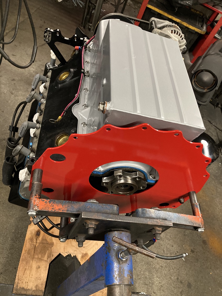
I've always suspected they could be off, but never went to the hassle of driving them a couple hours away and waiting a week to have them checked. Had the engine out to weld a new bung into the oil pan, now i've got all winter play with little stuff i never seem to have time for...

shopmulebottomend.jpg


Grant
 
I've always suspected they could be off, but never went to the hassle of driving them a couple hours away and waiting a week to have them checked. Had the engine out to weld a new bung into the oil pan, now i've got all winter play with little stuff i never seem to have time for...

View attachment 1715612759

Grant


LOL...now I get that bobweight number.
 
Ram says they balance to .5 ounce inch, so about 2.5 grams at the radius i'm working with. That has me feeling pretty good about the 2 gram resolution i'm getting from the cold rolled shafts. I decided to install a shouldered stud in the #6 cover bolt position, i'll make a balance weight to install on that stud.

To adjust parallel of the support shafts, i just lay the face of the flywheel on them and check to see if it rocks, then adjust until it doesn't rock. Front to back level I adjust with a digital level, side to side i level by letting the arbor roll on the support shafts until i'm satisfied it has an equal tendency to roll in both directions.

Here's a pic of my oil level sight tube after I replaced that lower bung. The original brass fitting was soldered in place and had some damage that caused it to drip occasionally when the car sat for extended periods. This time I welded in a steel bung to make the fitting replaceable...

shopmulesightgauge.jpg


This car uses a pcv valve for crankcase vacuum, so it needs to be sealed up pretty well as even small leaks will hurt your ability to pull a vacuum. In the upper right you can see an aluminum plug that seals off the original dipstick hole, crossing the dipstick off the list of potential air leaks. The crankshaft seal lips have also been reversed to prevent sucking in air. With a large check valve sealing off the separator tank vent hose, it's sealed good enough for the pcv valve to pull 15"Hg in the crankcase while cruising down the hiway @ 2500 :)

Mini starter mesh was also a little tight, probably 1 out of twenty twists of the key resulted in the drive not engaging the flywheel teeth. Took advantage of the engine being upside down while working on the pan, made a shim and trimmed out the starter hole in my block plate. Crossed that off my list of little things to fix a few days ago.

Grant
 
Ram says they balance to .5 ounce inch, so about 2.5 grams at the radius i'm working with. That has me feeling pretty good about the 2 gram resolution i'm getting from the cold rolled shafts. I decided to install a shouldered stud in the #6 cover bolt position, i'll make a balance weight to install on that stud.

To adjust parallel of the support shafts, i just lay the face of the flywheel on them and check to see if it rocks, then adjust until it doesn't rock. Front to back level I adjust with a digital level, side to side i level by letting the arbor roll on the support shafts until i'm satisfied it has an equal tendency to roll in both directions.

Here's a pic of my oil level sight tube after I replaced that lower bung. The original brass fitting was soldered in place and had some damage that caused it to drip occasionally when the car sat for extended periods. This time I welded in a steel bung to make the fitting replaceable...

View attachment 1715613894

This car uses a pcv valve for crankcase vacuum, so it needs to be sealed up pretty well as even small leaks will hurt your ability to pull a vacuum. In the upper right you can see an aluminum plug that seals off the original dipstick hole, crossing the dipstick off the list of potential air leaks. The crankshaft seal lips have also been reversed to prevent sucking in air. With a large check valve sealing off the separator tank vent hose, it's sealed good enough for the pcv valve to pull 15"Hg in the crankcase while cruising down the hiway @ 2500 :)

Mini starter mesh was also a little tight, probably 1 out of twenty twists of the key resulted in the drive not engaging the flywheel teeth. Took advantage of the engine being upside down while working on the pan, made a shim and trimmed out the starter hole in my block plate. Crossed that off my list of little things to fix a few days ago.

Grant


I need one of those oil level thingys. What is that made of??? Looks like plastic and it would be hard to see the oil level.
 
It is a little hard to see oil level when the Mobil1 is brand new, the tubing is PTFE which is basically Teflon. Comes in many colors, but clear isn't one of them. If you need some, i've still got a couple feet of "natural" on hand.

I originally tried a clear tubing that didn't stand up to the heat of a nearby header tube. Worked fine for a couple weeks but melted one hot day while i was driving. Didn't leak while driving because of the crankcase vacuum, but shortly after I turned the engine off, it started dumping oil all over Tractor Supply's freshly sealed parking lot in front of a couple dozen of my car buddies. Had I thought of it, could have just switched on the electric pump to keep it from leaking while i rounded up something to plug the hole. Instead, ended up with a huge mess that of course started running in the direction of a catch basin. Had to buy about $80 worth of oil and a big sack of floor dry.

Grant
 
This dual friction disc was only out 1g @ ~ 5"...

balancefixture7.jpg


Found that if I set up the fixture on the concrete floor instead of the bench plate, resolution improved to 1g with the cold rolled shafts. The 65lb bench plate plugs into a single 2" square receiver style socket in the bench, turns out there was a little flex when the parts were rolled from one side to the other. Need to make a slightly larger dia arbor to balance my full face iron discs.

I also opened up the center hole in the block plate, something I wanted to do to improve flywheel/clutch cooling for when I do 2nd gear launches. Thought about adding an exhaust eductor to pull fresh air thru the bell as well, but not sure I want to send clutch dust thru my big Magnaflow muffler...

shopmuleblockplate.jpg


Grant
 
Last edited:
-
Back
Top