HIGH RESISTANCE IN CIRCUIT -- PLEASE HELP!!

-

Gublakhan

Active Member
Joined
Apr 18, 2015
Messages
29
Reaction score
1
Location
Santa Monica
Hello All,

I’m having some frustrating issues with electrical / ignition wiring on my 66 Dodge Dart 270 (225) Slant 6. The headlights and dash lights dim at idle and brighten on acceleration as well as varying voltage with acceleration and de-acceleration. After reading quite a few posts here I’ve determined that I have high resistance some where in the circuit.

Regarding the state of things, I’ve replaced the wiring harnesses last year (engine, dash, taillight) with original reconditioned 66 Dodge Dart wiring harnesses including bulk head and fuse box.

Last week, I had to replaced the alternator and regulator and luckily they were both under warrantee from Oreilly’s. I upgraded the regulator to the $50 mechanical one, since I’ve had to replace the solid state ones numerous times. Also, I replaced the starter relay from Oreily’s and a new ballast, headlight and ignition switch from Rock Auto. I have also restored the dash cluster with a new circuit board, new 12-5volt mechanical regulator, reconditioned gauges (temp, fuel, ammeter), and replaced all bulbs. I’ve wired separate grounds for the headlight switch, dash cluster, and ignition switch as well as for the fuel tank.

The BIG question is where and how to track down the high resistance in the circuit without ripping out the harnesses again? Is it possible, that the alternator and regulator are defective – they’ve been in the car a week? Also, this problem existed with the old harnesses, but it was way more extreme. I should also mention that in the last three years I’ve installed remanufactured alternators from Oreily’s – probably four or five in three years.

Below are voltage tests that I performed this morning with my multi-meter.

Tests performed with Engine running at idle in Park for 20min:
Without load on battery: 14.30v
- Ammeter (Batt) post: 14.25v
- Ammeter (Ignition) post: 14.41v

With load on battery: 12.80v
- Ammeter (Batt) post: 12.45v
- Ammeter (Ignition) post: 12.30v

Tests performed with engine off and ignition switch turned to on:
One probe on positive battery post and other probe on regulator post (Ignition) reads: 1.32v
One probe on positive battery post and other probe on ballast post (Ignition) reads: 1.19v
One probe on positive battery post and other probe on ballast post (Coil) reads: 3.72v
One probe on positive battery post and other probe on alternator post (Ignition) reads: .36v
One probe on positive battery post and other probe on alternator post (FLD) reads: 12.31v
One probe on positive battery post and other probe on starter relay post (Batt): .08v
One probe on Ammeter Post (Batt) and the other probe grounded reads: 12.10v
One probe on Ammeter Post (Ignition) and the other probe grounded reads: 11.97v

Same above tests performed with headlights on:
One probe on positive battery post and other probe on regulator post (ignition) reads: 1.82v
One probe on positive battery post and other probe on ballast post (Ignition) reads: 1.66v
One probe on positive battery post and other probe on ballast post (Coil) reads: 4.14v
One probe on positive battery post and other probe on alternator post (Ignition) reads: 1.02v
One probe on positive battery post and other probe on alternator post (FLD) reads: 12.12v
One probe on positive battery post and other probe on starter relay post (Batt): .40v
One probe on Ammeter Post (Batt) and the other probe grounded reads: 11.40v
One probe on Ammeter Post (Ignition) and the other probe grounded reads: 11.20v

Test performed with engine on at cruising idle:
One probe on negative battery post and one probe on regulator mount (ground): .02v
One probe on negative battery post and other probe on alternator (ground): .01v

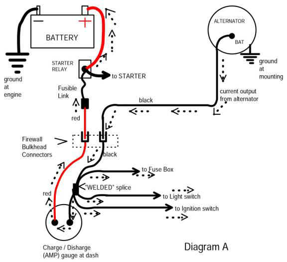
Also, I should note that I burned up a solid state 12-5v regulator on the dash cluster yesterday while wiggling wires at the bulkhead (engine was running). This pointed my attention to the factory splice near the ammeter where the headlight / cluster regulator feed are connected to the ignition, but no direct connection to the bulkhead. I'm now back to using a mechanical 12-5v cluster regulator.

If there is anyone who can make sense of all this, I would hugely appreciate it!!
Thanks in advance for any advice, help or guidance in troubleshooting the mess!
 
One probe on positive battery post and other probe on regulator post (Ignition) reads: 1.32v

This right here is telling, and what I've written so very much about. You have voltage drop in the harness and connections from the VR to the battery. It MIGHT be right in the ignition switch. The "original" path is

Battery.....fuse link......bulkhead connector (RED ammeter wire)......ammeter.........BLACK ammeter wire to welded splice.........to ignition switch connector........through switch.......back out switch connector on dark blue ignition run (IGN1)..........back out bulkhead connector.........to ignition, VR etc.

Any one or some or all of those points in the circuit can be causing a drop.

One way 'around" it is to cut loos the blue "ign run" wire coming out of the bulkhead connector. Use the bulkhead side to trigger a relay. Feed the relay (fuse or breaker) off the starter relay stud, and then the relay will feed the engine harness side of the blue wire.

If you find that FIRST other things may fall into place, but that is a "biggie" to start

You can find it or them the same way you found this reading. Clip a long wire to battery PLUS and to one meter lead, "insulated." Take your other meter lead and probe the "path" listed above, with key "in run"

If you have "points" ignition and are concerned about burning them, bump the engine until the points are open.

HOWEVER you need a LOAD on that circuit. The VR "might" be enough. You could also hook a headlight to the "key" side of the ballast to load that circuit. In fact, you could run a long clip lead from the ballast terminal around to the dimmer switch and light up one set of headlights.
 
have you check and or cleaned your grounds ie battery to eng. battery to body and eng. to body a poor groung may be the problem many forget how importand these ground connections are and they do neesd attention on our older cars have solved many ploblems by just cleaning the grounds
 
Hi 67Dart273

Thanks so much for offering this info. It's super helpful!

I just have a few questions... once I start probing those suspect points, what am I actually looking for? A drop in voltage? In general, when I'm reading the voltage, it tends to fluctuate plus or minus .10-15v. Also, some of these points are quite difficult to locate. For example the welded splice, any suggestions how to check that? Also, the ignition switch connector, do I just try to probe where the connector connects to the switch posts?

Also, I'm a little confused with the "work around" you explained... Take the blue "Ign Run" wire -- I'm assuming that's the heavy gauge blue with tracer wire (fusible link) from the bulkhead and disconnect it from the starter relay (batt) stud in the engine compartment... (Attached is a photo for reference) The second part I don't completely understand, "Use the bulkhead side to trigger a relay. Feed the relay (fuse or breaker) off the starter relay stud, and then the relay will feed the engine harness side of the blue wire" Do I take another relay (fuse or breaker) and connect it to the starter relay stud and then to the blue with tracer (fusible link) wire? Is this right?

Btw, I've upgraded to an OEM electronic ignition system.

Many, many thanks again for your help and advice -- I so need it at this point!!

Bulk head blue wire.jpeg
 
have you check and or cleaned your grounds ie battery to eng. battery to body and eng. to body a poor groung may be the problem many forget how importand these ground connections are and they do neesd attention on our older cars have solved many ploblems by just cleaning the grounds

Yes, I've checked and cleaned the grounds.
When I check the grounds with the multi-meter, it's reading .01-.02 which I means the ground contacts are good, right?

Thanks for your input!!
Electrical troubleshooting is exhaustive : (
 
Okay, so I made some more tests based on 67Dart273's suggestions and below are the results... A bunch of numbers that I'm not sure what to dow with, ugh!! Any help or suggestions much appreciated!!

All tests performed with engine off and ignition switch turned to ON with one Probe connected to the positive battery post and the other probe connected to the ignition switch..

(ACC) Black reads: .63v

(BATT) Red reads: .61v

(ST) Yellow reads: 12.51v

(IGN 1) Blue/Blue w/ tracer reads: .63v

(IGN 2) brown reads: 3.66v

All tests performed with engine off and ignition switch turned to ON with one Probe connected to the positive battery post and the other probe connected to the Ammeter…

(BATT) post reads: .20v

(ALT) post reads: .52v

All tests performed with engine off and ignition switch turned to ON with one Probe connected to the positive battery post and the other probe connected to the bulkhead under dash connection…

Batt (RED) .15v With Headlights on: .55v

Alt (Black) .60v With HeadLights on: 1.12v

Ballast / Regulator (Blue with tracer) 1.0v with headlights on: 1.46v

Ign 2 (Brown) 3.68v with headlights on: 4.0v

At fuse block all contacts read: .56v
 
EDIT........posted this before your last

No if you add a relay, don't use the fuse link!!!!

Cut the blue "run" wire (ign1) which comes out of the bulkhead and feeds one end of the ballast, and the IGN terminal of your VR

"What you are looking for."

Here's the thing...........that circuit path I described.......is the "path" of wandering road between the battery and the VR IGN terminal. In your car, AFTER that path "comes out" of the bulkead connector on the "ignition run" wire and "on it's way" to feed the ballast and the VR, those are pretty much the LOAD on that circuit.

INSIDE the car, the LOAD on that circuit is pretty much "stuff" that is ONLY powered in "run." Like the gauges, the warning lights, etc.

So "to look for" is this: As you go down that path.......in the wiring.......passing the "intersections" in the harness and connectors...........any LOADed circuit, that is, one drawing CURRENT, will LOAD DOWN the supply voltages as it "passes" more and more connections and terminals which have a bit of RESISTANCE

So what you need to do is to check voltage down that "road" and measure each point which you can access. For example, getting to the ammeter might be hard, getting to the ignition switch might be easier

So if you measure drop between battery + and the ignition switch power going INTO the switch, and then the blue "run" wire coming OUT of the switch, if the reading is 1/2 volt lower, then you have 1/2 volt drop i the switch and connector.

Also take apart and inspect your bulkhead connector. Many of the problems are "right there."
 
(ACC) Black reads: .63v

(BATT) Red reads: .61v

(ST) Yellow reads: 12.51v

(IGN 1) Blue/Blue w/ tracer reads: .63v

(IGN 2) brown reads: 3.66v


Where is the red? This on the back of the ignition switch? That is a LOT!!!

Brown is not relevant here
 
Batt (RED) .15v With Headlights on: .55v

Alt (Black) .60v With HeadLights on: 1.12v

Ballast / Regulator (Blue with tracer) 1.0v with headlights on: 1.46v

Not sure where this RED point is

The alternator reading shows drop through the bulkhead and ammeter. That's a LOT

The ballast is REALLY a lot

I'm going to guess that the main problems are in your bulkhead connector, and also possibly the ammeter.
 
To put this into a bit of perspective, let's say your regulator is "trying" to regulate properly at 14V In other words that's it's "setting." You are showing a 1.46 drop there at the ballast. This is going to get ADDED to the 14V of the VR so 14V + 1.46 is 15.46 is what the battery will be charging at, way too much.

I realize it's easy to get lost in this

This is yet another candidate for the "Mad electrical" article:

MadElectrical.com - Electrical Tech
HERE:
Catalog

And in there is this simplified diagram:

amp-ga18.jpg


This shows the simplified power in the car. Battery.........fuse link........through bulkhead........through ammeter..........to "welded splice"......and branching off to headlights, ignition switch, etc.

It does not show "back out" through the bulkhead to the ballast resistor. This is just simply one more terminal in the bulkhead connector.

ALSO: It is RARE but there has been cases where the welded splice has come apart. This is a factory splice in the black ammeter wire, wrapped in the under-dash harness a few inches from the ammeter, tucked up with the cluster.

If your troubleshooting indicates this might be it, you will have to pull the cluster, unwrap and cut open the harness, and inspect. Save that for "last" LOL
 
Where is the red? This on the back of the ignition switch? That is a LOT!!!

Brown is not relevant here

Hi 67Dart273
Thanks for all your help so far!

To answer your question...
The red wire is on the back of the ignition switch (Batt) connector reading .61v

To clarify the other "Red Point" is at the bulkhead inside the car -- Batt (RED) .15v With Headlights on: .55v

Also, i think its important to note that the readings on the multimeter fluctuate quite a bit... It's not always exact, so I try to take an average reading.

I will take off the bulkhead and clean it tomorrow.

Thanks again for all your help!!
 
Yup I'd start there at the bulkhead connector for certain
 
Hello, 67Dart273
So I removed and cleaned the bulkhead -- it actually looks in pretty good condition. There's no corrosion or broken or loose connectors. However, I did notice that the black padding gasket was not complete and broken around the female part of the bulkhead that seals to the firewall. Also, I'm missing two of the black gaskets for the male connectors. How important are these?? Do you have any suggestions what to use to replace this seal / gasket? Also, does the bulkhead "ground" to the firewall via the female bulkhead connector? If so, I imagine it's super important for the seal to be clean and tight?

While doing all this, I also realized that the ground cable from the transmission housing to the firewall had seen better days.. It was corroded and dirty, so I took it off cleaned and added some dielectric grease to the contact. I continued to check the ground at the right headlight and it was clean but loose, so I tightened that one up and added some grease as well.

Thanks again for all your help!!!
 
Hello again,

I managed to make some DIY bulkhead gaskets with some gasket material creating a nice snug fitting to the firewall. I put everything back together, it started right up, but the ammeter was pegged to the right with my multi-meter reading 14.5volts. A little concerned about the ammeter, I put my fingers on the posts. They were smoking hot! I turned off the car and waited for it to cool down, about 10min, then tried to start it again -- DEAD. I checked the ammeter posts, the battery side was reading voltage, but the alternator side not. I also checked the ignition switch, nothing. I did a few more tests and determined that I either the ammeter failed or the factory splice failed. I continued to pulled the dash cluster to first investigate the ammeter... Visibly the gauge looked fine -- a little plastic melting inside around the post contacts, but no visible breaks. I ran a few more tests to see if current was crossing, but unfortunately not -- the ammeter failed.

Two questions, why are the leads to ammeter heating up? Is this because there is resistance in the circuit? Also, how safe is it to bypass the ammeter knowing that the wires are most likely going to heat up again? I've decided that I will do the MAD bypass, but I'm concerned that the bypass is not going to solve the resistance in the circuit problem. Also, what's the possibility that the resistance is generated by the alternator or another accessory? I'm now not so convinced it's the bulkhead - it's clean, snug and seems secure.

Any help with this frustrating mess, would be incredibly appreciated : )
 
It sounds like you somehow generated a short. Interesting, as you say the battery still showed 14.5 which is "somewhat normal" You may have blown up the fuse link

HOW TO TEST without blowing things up

Now that you "might" have a short, when you get to trying to resolve, PROTECT the car from further damage. One way to do this is to take a "heavy" wattage lamp such as a junk tail/ stop socket. With an 1157 bulb, twist the two socket wires together, and connect a second wire to the shell. One way to do that is with a hose clamp. Connect the shell to ground, and WITHOUT hooking up the battery ground cable, hook the "twisted" wires to the battery NEG post. This will create a limiting device. Go around and make certain everything is turned off, including any lamps or dome / courtesy lamps. If the tail light glows, you have current flow. You can go 'round and look for the short.

Another way is to temporarily substitute a fuse holder for the fuse link.

No idea what you might have done. If you have been "moving" stuff, look and inspect the alternator main output post, the bulkhead connector (you didn't "repin" any terminals eh?) and the ammeter connections, which may have moved around, broken, shorted, etc.
 
Thanks 67Dart273!

I actually have a test probe that works the same way, but I've been lazy. That said, I took it out today and tested everything... The only suspect contact was the black ignition post (ACC) which splits off at the splice to the windshield wipers switch, fusebox (heater), turn signals and voltage limiter feed for the dash cluster. Strangely enough, the circuit was not complete on the ignition switch until I engaged the turn signals. Other than that, the car seems short free.

However, I'm still trying to understand why I still have high resistance in the system .. After everything I have done, I'm still reading 1.23v from the FLD post on the regulator when putting the other probe on the battery positive with the ignition in run but engine off.

Thanks again for your help.
 
About all you can do is "chase it back" down that road point by point.

With that condition EXACTLY, what is the votage from the battery to the IGN run output of the ignition switch?

From the battery "right at" the ignition switch to the "IGN run" coming out? You simply have to follow it "down that road." And it might not be all in one spot.

"Major test points:"

The red wire coming in through the interior side of the bulkhead connector

Each side of the ammeter

The battery "going into" the ignition switch

The "run" wire "coming out" of the ignition switch

Let's say for example that the reading is great between battery post and the red ammeter wire right at the ammeter. Let's say that measures .05V, "nearly nothing."

Let's say the black ammeter wire right at the ammeter reads the same.........05 to the battery

But yet, let's say the battery supply "going into" the ignition switch is "down" some maybe .7v, but whatever, is MUCH MORE than the .05.

What IS BETWEEN the ignition switch connector and the ammeter?

Only one thing.........the in harness splice. In the black ammeter wire.

=========================

Or, let's say you measure right at the ign switch "battery" wire and it's maybe, .5. That's "some" buy not your "more than a volt" you are getting

You measure on the IGN "run" coming "out" at the ign switch. It's let's say 1V. That means that you have a .5 drop "going into" the switch and ANOTHER .5V right inside the switch (or the connector). You have to fix each and every one.

Your other alternative is to use a relay to supply the IGN system.

Thanks.
I'll keep searching for it.
 
-
Back
Top