not charging, why?

-

1969dodgedartgt

Well-Known Member
Joined
Oct 8, 2010
Messages
1,010
Reaction score
4
Location
CA
I read 15V coming out of my alt. I checked the wires going into my regulator, got 11.56V coming in regulator from batteries 12.4 V, and field wire is good. I just replaced the regulator but its still not charging.

my volt gauge shows discharge and the voltage across battery when running is just 12.4.

I'm at a loss. what should I be looking at?


story behind how this started, it was charging fine yesterday before I replaced my speedocable. dont know what I might have done to mess things up with that.
thanks
 
You've got a fault (open circuit) in the main A1/A1-A charge line that runs from the alternator B+ (output) to the bulkhead disconnect, to and through the ammeter, back out the bulkhead disconnect, from there to the largest terminal on the starter relay, and from there to the battery positive. Get the wiring diagram and check every segment of this line, keeping in mind the fault may be an open circuit in the ammeter itself since all current flows through it (easy test for this: with engine off, turn the headlights on and watch the ammeter. If it moves leftward, the ammeter hasn't got an open circuit).

For now, to get the car back on the road, run a 10ga wire from the alternator B+ directly to battery positive.
 
Sure sounds like it. This is why there's so much stuff on the www about bulkhead connectors, undersized wiring, and ammeter failures. To complicate the problem further there are one or two welded splices IN THE HARNESS under the dash, and I've seen 3 or 4 of these fail over the years.

check the wire from the alternator to the terminals that end up going through the bulkhead. Particularly check the ENDS. Take the bulhkead connector apart and examine. Get up under the dash and check the ammeter connections are tight. Sometimes wiggling/ pulling on the harness here and there will make connections come and go, and give you a clue as to where the problem lies.
 
thankya, doesn't look like the ammeter, time to test some wires.


ouch, that wire splits off everywhich way on the instrument panel side, goes to starter switch, horn relay, ammeter, fuse box, headlight switch.
so I'll only check the path through the ammeter....
seems like since the ammeter is reading something, I just need to check from ammeter to battery? or since the ammeter is not reading the charge I should check from B+ output to ammeter?

I dont understand how the ammeter can read a discharge and not a charge if it only has that one wire going through it.

I hate working under my dash.... and trying to get that instrument panel down... grrr
 
Ok here's how I'd do this:

Run a TEMPORARY wire (may later be permanent) directly from the alternator output stud to the battery, use at least no10, preferably larger, no8

Now with the engine running "low / med cruise" and with time for the battery to "come up" check the charging voltage and see if it's normal.

Now check --just to be sure you don't have multiple troubles-- check the voltage drop across the ground path and the harness Do this by----

Put a probe DIRECTLY onto the battery neg. post, the other directly onto the regulator case. (engine running as above). You want a LOW reading, zero is perfect. If the reading is over .2v (two tenths) it's too high and you have a ground path problem. Add a ground wire from the firewall/ regulator mount to the block or to the battery

Next, check the drop across the positive harness. Stab a probe directly onto the battery positive post, and the other onto the regulator ignition feed. Once more, lower the better, not over .2V at the most.

Now use your head here. If this is high, it may be part of the original problem. That is, the ACTUAL voltage to ground coming out of the bulkhead from the ignition switch may be low.

NOW IS THE time to get out the diagram and do some looking

Here's the diagrams from "My Mopar." These are NOT exactly correct

http://www.mymopar.com/downloads/1969/69DartA.jpg

http://www.mymopar.com/downloads/1969/69DartB.jpg

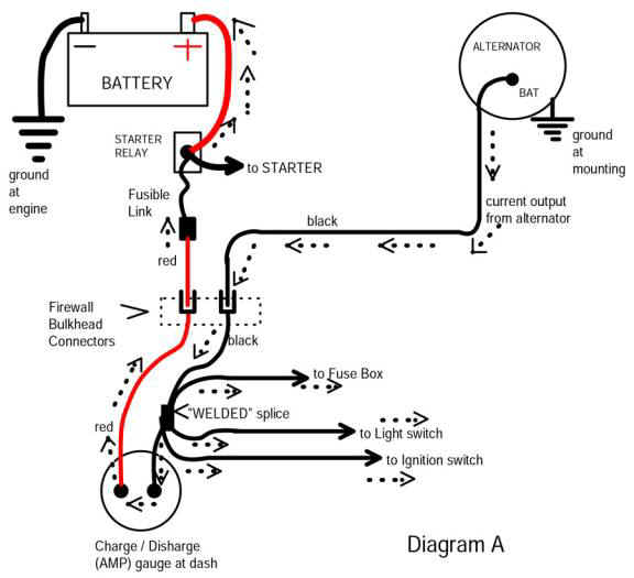
Starting on schematic "B" follow the thick wire off the alternator output, up the page to the bulkhead connector noP. It goes to the mating connector P and off to the left of the page.

On schematic A it comes in, down, AND TO AN IN HARNESS SPLICE, the thick wire continues down the page and to the ammeter

So far the main things that could be AFU are:

A break in the wire coming off the alternator stud right inside the connector, there MAY be a fuse link in that line, and the bulkhead connector could be "done." Last, the eyelet connector at the ammeter could be broke inside, or loose right at/ in the ammeter

Also note that COMING OFF that big spice a wire going to the left FEEDS THE IGNITION SWITCH. If that splice has come loose, you will not get field current to the alternator, AND IT MAY BE INTERMITTENT, meaning that the car may start, die, start again, charge sometimes or not.

Now, back to the ammeter. notice the large red coming off, follow it out to the other page, it goes though no J of the bulkhead, on to the starter relay, and finally, the battery.

ONCE MORE we can have a bad connection at the ammeter, a broken eyelet connection inside the molded end, and a bad connection through the bulkhead, and possibly a bad fuse link

Here's a very good article from "Mad Electrical" which outlines these types of problems:

http://www.madelectrical.com/electricaltech/amp-gauges.shtml
 
I agree with everything 67Dart273 says except the part about the MAD electrical article being "very good". It is not. It's written by a bunch of Chevy-heads who don't know nearly as much about Mopar charging systems and underhood circuitry as they appear to want to think they do.
 
I agree with everything 67Dart273 says except the part about the MAD electrical article being "very good". It is not. It's written by a bunch of Chevy-heads who don't know nearly as much about Mopar charging systems and underhood circuitry as they appear to want to think they do.

What part don't you like, Dan?

It outlines several chronic problems with Mopars:

The awful, inadequate design of the bulkhead connector, which I had problems with back in the day

The fact that some? many? ammeters depend on the plastic of the dash itself to clamp the wire connections onto the ammeter studs, and in fact, hold the entire internal connections together

Illustrates the "in harness" splice, which SHOULD never have been a problem. Over the years, I've found several failures.

So what is it you don't like about the article?
 
well I traced things down to voltage being lost across he bulkhead
I cleaned the connection on the engine side (which I did unplug yesterday because I noticed the bottom part was not fully seated). Then when I went to retest things the alternator was not putting more than 12 volts out. I pulled that cheap remanufactured SOB and took it to a shop to have it tested, they agreed it was bad. So I've got a buisness transaction lined up with a friend of Dans to get a new Chrysler alternator.

I may go physically throw the old alternator at the shop I got it from, without doing any damage to the shop. When I got this thing I asked them to rebuild it and they put in a remanufactured one.

I may do some of your tests later, 67Dart, thanks for the help guys..... hopefully the next post I put on here will be a big thumbs up for all is well with the new alternator connected.
 
threw 'new' 40 year old Chrysler alternator in there and still not charging, grrrrr. Dont have time for this now, must grade now.
I'll spend time this evening playing with it o.0
 
The system is really simple. Components are alternator, voltage regulator, ignition switch, and four wires. Check for line voltage at voltage regulator "IGN" terminal with key on and engine stopped. If none, fix the wire between the ignition switch and regulator "IGN" terminal, or the ignition switch itself. If you do find line voltage at "IGN" terminal, then check for voltage acros regulator "FLD" terminal and ground with engine running. If none, replace voltage regulator. If you do find voltage at regulator "FLD" terminal, check for voltage at alternator "FLD" terminal with engine running. If none, fix wire between regulator and alternator "FLD" terminals. If you do find voltage here, then check for 0v between alternator B+ output terminal (the threaded stud) and battery poz with engine stopped. If you see 0v, your car is possessed or it is in fact charging and you're not measuring it correctly. If you see anything other than 0v, then fix the wire from the alternator B+ to the firewall main disconnect and the big terminal on the starter motor and the big terminal on the starter relay and battery poz.
 
What part don't you like, Dan?

The part I do like is that they identify a real potential problem. The part I don't like is the way they misrepresent its likelihood and present workable but halfaѕѕed, schlock "solutions". A job worth doing is worth doing right. This applies not only to their article about Mopar ammeters, but their article about headlamp circuitry (a subject about which I know enough more than they do to pass sturdy judgement on the quality of their advice).
 
heres what i'm seeing

Engine off:
voltage across bat (no load) 12.28V
bat with key on 11.9V
voltage at IGN term with key on 10.33V
.3-.1 Ohm across field wire btwn VR and alt

with engine running :
11.9V across Bat
10.16V bwtn VR field term and bat -
9.93 V bwtn alt field and bat -
31 V across Bat - and alternator Bat +!!! ( thats at about 900 rpm)
31 V bwteen bulkhead A1 line (engine side) and bat -

even with this 31V my ammeter in dash shows discharge. I need to move my car to get my door fully open if I want to check voltages in cabin.

looks like I got another bad alternator which I just shoved some good $$ for? is something in my system killing my alternators....????

(time to go for a run to discharge any excess stress this is building in me :) )
ran, reading "the peterson automotive troubleshooing and repair manual" on troubleshooting the charging system now.
 
EDIT----------------------

You said:

31 V bwteen bulkhead A1 line (engine side) and bat -.

THIS might be a huge clue. What are you calling "A1"?

In other words what two exact points were you probing?
=============================================================================
(The pre - edit - post):

!!!! NO NO NO NO !!! Your alternator is JUST FINE. The problem is that the ALTERNATOR output is DISCONNECTED from the BATTERY

Your car is the shining example of all the "talk" about problems with bulkhead connectors, the dreaded ammeter, and one other trick, the "in harness splice."

You have a diagram? You need to trace the PATH from the alternator output stud back to the battery. SOMEWHERE in there you are losing a connection.

Some things:

The bulkhead is a BIG suspect, but ALSO suspect factory wire ends (starting right at the alternator) that have the factory molded rubber cover--they can break inside

Check and suspect the bulkhead connections---the alternator output goes INTO the bulkhead on one terminal, connects inside, and to and through the ammeter, and COMES BACK OUT on a different terminal.

So it could be two terminals in the bulkhead. AND

it could be the ammeter, or the wire ends AT the ammeter, AND

it could be that the factory "welded" in--harness splice has opened up

Go back up the page and read my post, look at the diagrams.

DO YOU HAVE a service manual??

So let's repeat:

From this page:

http://www.madelectrical.com/electricaltech/amp-gauges.shtml

comes this diagram:

FOLLOW from the alternator. (wire end) from the alternator output stud, to the bulkhead connector and into the car--------into the harness welded splice--------to the ammeter (wire end) through the ammeter (wire end) out the ammeter (red wire) BACK through the bulkhead-----fuse link------to starter relay

You have to pretty much check all of that circuit START WITH THE ALTERNATOR wire and go towards the battery

amp-ga18.jpg


Once again repeat---refer to the diagrams I posted or else get buy steal find a service manual for your year

HERE is a photo of your bulkhead connector. "P" is where the great big black wire coming FROM the alternator output is. Probe this terminal inside and out, with the car running, it should be the same voltage as the ALTERNATOR. If it's high on the outside, low in the inside, obviously the connector is bad. PULL IT APART and inspect and clean it

"J" is where the "big Red" comes back OUT to the battery. If you see 30 some volts back at P and 12 or low here at J, then the problem is either in the bulkhead or inside the car.

Interior side:

3151g68.jpg


Firewall side:

nqtwtc.jpg
 
k,
i 'field tested' the alt by removing the field input to the alt, taping it off to prevent grounding, and connecting a wire between the alt out B+ and the alt field in. Thereby removing the regulator from the system. readings are about the same:

12.12V across bat when idle.
30V between alt B+ and Bat negative terminal.

I guess I have a problem in my A1 line (cabin side) and a bad alternator.
I dont hear any bad noise from the alternator.


errr sorry what I was calling the A1 is actually the r6 line, I have a service manual or two. Let me go check voltage coming out of J right now...
That 30 volts is not a prob?

oh geez, shes charging again, f_n bulkhead. I saw voltage being lost across it last week and it was going from 30 to 12 this week. unplugged the engine side, scraped the p connector with a screwdriver plugged back in and it works.

now since its been sitting for a week and raining for a week I saw some blue smoke when I first started, lasted about 1-3 minutes, and the drivers side carpet is all wet :(.

warm weather come, stop raining so I can fix my leaks. I've had her covered too.

eh whatever. Thanks so much Dan and 67Dart273, you guys deserve honorary gold memberships!!!

let this thread end now. it was fairly educational :p
 
Yes, it sure as hell is. the alternator output stud should NOT be much different from battery voltage. I don't have a '69 diagram, I was using, I believe, a 70


While you are checking, see if you can get clips up in the ammeter terminals and see what they run while the engine is running/ charging.


-------------Something just occurred. BECAUSE you are getting battery power to car interior (look at the simplified MAD diagram---red coming in from the battery, going to the ammeter, and to the "harness splice"

HERE ARE YOUR POSSIBILITIES:

bad connection at P on the bulkhead connector

OR

a bad connection at the "in harness" splice

THAT IS ALL THAT IS LEFT
 
on a final note I'd like to find nice clean solutions to that bulkhead problem. the drilling idea does not please me. I will look around, I think I saw something on valiant.org
 
it doesnt read 30 volts now, looks like once the system was all complete things are 'regulated' well
 
The system is really simple. Components are alternator, voltage regulator, ignition switch, and four wires. Check for line voltage at voltage regulator "IGN" terminal with key on and engine stopped. If none, fix the wire between the ignition switch and regulator "IGN" terminal, or the ignition switch itself. If you do find line voltage at "IGN" terminal, then check for voltage acros regulator "FLD" terminal and ground with engine running. If none, replace voltage regulator. If you do find voltage at regulator "FLD" terminal, check for voltage at alternator "FLD" terminal with engine running. If none, fix wire between regulator and alternator "FLD" terminals. If you do find voltage here, then check for 0v between alternator B+ output terminal (the threaded stud) and battery poz with engine stopped. If you see 0v, your car is possessed or it is in fact charging and you're not measuring it correctly. If you see anything other than 0v, then fix the wire from the alternator B+ to the firewall main disconnect and the big terminal on the starter motor and the big terminal on the starter relay and battery poz.


Thanks Dan this just allowed me to identify a bad VR, I wish this info was in one of those books you recomended.
 
-
Back
Top