ESP47
Well-Known Member
Car is a 68 Barracuda and I'm using a stock in dash rallye tach. I'm running a Blueprint 408 and it came with this ready to run distributor. I'm also using an MSD blaster 2 coil.
The PDF says: It also comes with a fully adjustable mechanical advance, vacuum advance, magnetic pickup trigger, and a high-output circuit board module with digital tachometer output.
I'm not utilizing the tach wire from the distributor. I just wired it up per the "Canister coil" section of the PDF and connected the tach's signal wire to the negative side of the coil.
Then I bought one of these tach filters from summit. https://www.summitracing.com/parts/cin-sn20
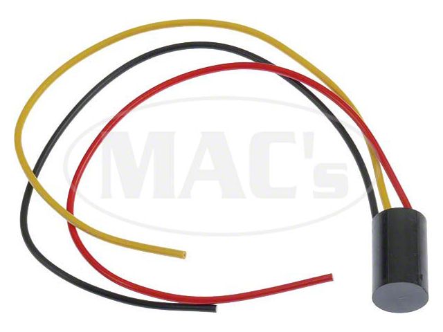
I wired the filter in line between the coil and the tach and to my surprise, the tach was operational and accurate.
I've only driven the car about 15 miles since I got the engine going and I noticed the tach no longer works. I have 12v coming in to the filter but 0v coming out. Filter is obviously blown but I'm not sure if it's blown because it's junk or because I've made some sort of mistake.
What do you guys think? If it looks like I'm wiring it up correctly, do you know of any better tach filters? I'm honestly not even sure if the filter is necessary or not but I'm a bit afraid to hook it up and try it without a filter because I'd hate to blow my tach and have to tear the dash bezel back out.
The PDF says: It also comes with a fully adjustable mechanical advance, vacuum advance, magnetic pickup trigger, and a high-output circuit board module with digital tachometer output.
I'm not utilizing the tach wire from the distributor. I just wired it up per the "Canister coil" section of the PDF and connected the tach's signal wire to the negative side of the coil.
Then I bought one of these tach filters from summit. https://www.summitracing.com/parts/cin-sn20
I wired the filter in line between the coil and the tach and to my surprise, the tach was operational and accurate.
I've only driven the car about 15 miles since I got the engine going and I noticed the tach no longer works. I have 12v coming in to the filter but 0v coming out. Filter is obviously blown but I'm not sure if it's blown because it's junk or because I've made some sort of mistake.
What do you guys think? If it looks like I'm wiring it up correctly, do you know of any better tach filters? I'm honestly not even sure if the filter is necessary or not but I'm a bit afraid to hook it up and try it without a filter because I'd hate to blow my tach and have to tear the dash bezel back out.


