Voltage Regulator Issues!!!!!!!

-

xLURKxDOGx

"An angel fat, at satan's feast"
Joined
Dec 27, 2013
Messages
4,361
Reaction score
1,753
Location
PHX
So, i was having issues with my lights pulsing for the last 6 months or so, i replaced the voltage regulator about 2 months ago, nothing changed. Out of curiosity i went and had autozone test the alternator, they said it and the voltage regulator were bad. I used the warranty and got another alternator and had them recheck it in the car, the alternator was good but it said the voltage regulator was bad. I picked up a new voltage regulator and it said the same thing, bad voltage regulator. Now, im getting 12.58 or so at the battery before starting and around 12.48 after starting and im getting roughly the same at the negative side of the alternator and 9amps at the FLD side while on idle. I was trying do some research and came to the conclusion that i needed 13.8 to 14.2 when the car is running but it just stays at 12.4 to 12.5. I just replaced the battery last month. I tried hooking a wire from the FLD on the alternator to FLD on the voltage regulator and it reads 9amps so im guessing it isnt from a bad wire because it reads the same either way. Any possible solutions or other things i can try or look for here, ive really been scratching my head on this one because i know NOTHING about wiring and need to get it sorted out before i put my new engine in on the 16th of this month.
 
How are you measuring this 9 amps?

And..........as usual..........what is it that we are working on?

"12 something" is not charging at all.

Test it ON THE CAR, and we can step you through that

I tend to divide things up into "sections" in no particular order

1.....Bad parts such as alternator / regulator

2....The output path IE charging path from alternator output, through bulkhead ammeter, etc and to battery

3....Field wiring, IE broken, poor connections, wiring improperly wired from some change, etc

4....Bad battery.

WE NEED TO KNOW what it is that you are working on................

this is a 1940's Cle--ota, or if you prefer, Toyotrac. It is an old Oliver "Cletrac" with a TOYota engine and 4 speed, a 1969 Mopar voltage regulator hooked to a Toyota alternator, and a GM HEI ignition module being triggered by the factory Toy distributor. The carburetor is off a '60's Ford Falcoon, and the governor is off the gasoline "pony" engine off a D2 Cat. It has a chrome hitch ball. The hood and other sheet metal is off a Massey wheel tractor

attachment.php


That is NOT what we are working on, but more importantly you did not mention what "is"

Sorry. Its a 1963 plymouth Valiant /6.
 
How are you measuring this 9 amps?

And..........as usual..........what is it that we are working on?

"12 something" is not charging at all.

Test it ON THE CAR, and we can step you through that

I tend to divide things up into "sections" in no particular order

1.....Bad parts such as alternator / regulator

2....The output path IE charging path from alternator output, through bulkhead ammeter, etc and to battery

3....Field wiring, IE broken, poor connections, wiring improperly wired from some change, etc

4....Bad battery.

Ive been measuring with a multi meter. I hooked up to ground and was getting power from the field side of the alternator and regulator while the car was running.
 
How are you measuring this 9 amps?

And..........as usual..........what is it that we are working on?


WE NEED TO KNOW what it is that you are working on................


LOL... you see... if you had bought that crystal ball at the flea market you wouldnt be having this problem......too late now its gone forever!
 
Ive been measuring with a multi meter. I hooked up to ground and was getting power from the field side of the alternator and regulator while the car was running.

Ok is this VOLTS you are measuring? Huge difference.

NEVER hook an ammeter from a voltage source to ground. If you don't hurt something in the circuit under test, you'll likely hurt the meter itself

If you can post a photo or at least brand and model of your meter, then we can be on the same page with that.

OK, NOW we know what you are working on, run a few tests.

FIRST make ABSOLUTELY certain the VR is grounded. Dismount it, scrape clean around the bolt holes, and remount tight with star lock washers.

With everything connected "normally" disconnect the VR wires and jumper them together. With a meter on the battery to measure battery voltage, IE set your meter on "volts" on an appropriate scale.

Start and run the engine and slowly bring up RPM. The ammeter in the dash should show increase charge, and the voltmeter on the battery should start to rise. Don't rev too high, keep voltage below 16V

If nothing happens, move your voltmeter probe over to the alternator output stud, and see what happens there, again bringing up RPM. See if voltage at that point goes up, and recheck if the dash ammeter shows any charge.

If the ammeter shows "centered" and the voltmeter goes way high, perhaps 17V there is a break in the alternator output wiring

If the voltage at the alternator stays down less than 13V, the alternator is not charging.

With the key "in run" and the engine either running or not (no matter) measure the voltage at the VR blue wire up where you jumpered it together. It should be "same as battery"

============================================

Next, we much make sure whether it's field wiring or the alternator

Get your self a clip (alligator) lead. Unhook the field terminal at the alternator, and hook your clip lead to the alternator field terminal. Run this wire over to the big stud (battery) on the starter relay. This duplicates much of the previous test, but eliminates the field wiring. With your voltmeter clipped to the alternator output stud, and bringing up RPM, if the voltage stays down around less than 12V, the alternator is bad
 
Also, visit over at MyMopar to get a shop manual and wiring diagram:

http://www.mymopar.com/index.php?pid=31

There is no 63 there, here's a 65 Plymouth manual

http://www.mymopar.com/downloads/servicemanuals/1965_Plymouth_Service_Manual.zip

Do NOT go by the electrical diagram "closely" in that book, some of it won't be correct

Here is an aftermarket diagram for 63:

http://www.mymopar.com/downloads/1963/63DartA.jpg

http://www.mymopar.com/downloads/1963/63DartB.jpg

"The basics" of the ??--69 charging system is below. What you have is the switched "ignition run" voltage (dark blue) comes from the ignition switch, through the bulkhead, and to one end of the coil ballast resistor. It branches off, and also feeds the IGN terminal of the voltage regulator. Through the regulator, out on green, and down to the field terminal of the alternator

The "batt" line coming out goes into the car through the bulkhead connector, through the ammeter, back out into the engine bay back through the bulkhead connector, through the fuse link, and to the battery.

http://www.mymopar.com/index.php?pid=78

pic1.gif

Thanks for helping, ill see what i can find out tomorrow. One thing i did notice off the bat was the 70 and below diagram has a chassis ground and the 63 diagram does not. I went out to look and for the hell of it i put a wire from the battery(black) to the FLD and it seamed to bring the charge up from 12.25 to 12.98 at idle and when i slowly brought the idle up in jumped into the low 13's. I took it for a spin around the block and jumped on the freeway to get it going and it wasnt pulsing and was a lot brighter, but when i came to a stop it wasnt as bright??? I looked at the voltage in the dash and it moved a bit over from the middle of the D into the C but not a lot. Does this mean anything significant???

Ill check the rest of the testing on the morrow.

Jake
 
the 70 and below diagram has a chassis ground and the 63 diagram does not.

You need to be much more specific, this is confusing. If you are talking about the VR the change was 70/ later VS 69 and earlier. What "chassis ground" are you referring to? What diagram are you referring to?

put a wire from the battery(black) to the FLD and it seamed to bring the charge up from 12.25 to 12.98 at idle and when i slowly brought the idle up in jumped into the low 13's. Jake

If you jumper a wire from the battery to the alternator field terminal, this causes "full tilt" charge, and while is a way to test, you should NOT drive the car this way.

Please re-read post 6. With a jumper from battery to alternator field, you should be able to bring up engine RPM and show a charge on the ammeter. You should show an increase on a voltmeter connected to the battery. If the battery is not "too dead" this voltage should come up above 14V

IF that is what you did, it sounds like the alternator is actually OK

If this is the case, make sure the field wiring is OK. RE-read post 6. Jumper the field to battery by jumpering across the two VR wires. That is, disconnect the VR and connect the two together. This should duplicate "full field" as above, and should result in a charge.

If that is OK, replace the VR. The VR MUST be grounded. Since you seem to be having trouble, I would REALLY check that the VR is in fact grounded. Scrape and clean around the bolts and flange, and use star lock washers.
 
You need to be much more specific, this is confusing. If you are talking about the VR the change was 70/ later VS 69 and earlier. What "chassis ground" are you referring to? What diagram are you referring to?


If you jumper a wire from the battery to the alternator field terminal, this causes "full tilt" charge, and while is a way to test, you should NOT drive the car this way.

Please re-read post 6. With a jumper from battery to alternator field, you should be able to bring up engine RPM and show a charge on the ammeter. You should show an increase on a voltmeter connected to the battery. If the battery is not "too dead" this voltage should come up above 14V

IF that is what you did, it sounds like the alternator is actually OK

If this is the case, make sure the field wiring is OK. RE-read post 6. Jumper the field to battery by jumpering across the two VR wires. That is, disconnect the VR and connect the two together. This should duplicate "full field" as above, and should result in a charge.

If that is OK, replace the VR. The VR MUST be grounded. Since you seem to be having trouble, I would REALLY check that the VR is in fact grounded. Scrape and clean around the bolts and flange, and use star lock washers.

The diagram of the 70 and below charging system you posted in #7. It has a FLD to the chassis and a FLD to the VR. The diagram on the 63 link you posted doesnt show that,so that is why i thought i would try running a wire from the battery, which i understand is different than a chassis ground. So, i went out this morning and the battery read 12.7 with the ignition off, but the wire from the FLD to the battery was still connected. I jumped the wires on the VR and got no rise in charge WITHOUT the wire from the battery to the alternator. I did notice that the readings were the same with the VR connected and disconnected and jumped WITH the FLD to BATTERY connected. Im sorry if this doesnt make sense, im a bit confused and trying to understand it all. It seams like unless that FLD to BATTERY wire is connected everything you suggested didnt charge. This alternator is 2 days old and said tested fine, im going to the junkyard here to look for a new engine harness, maybe theres a short in there.


Jake
 
OK, but I'm still a bit confused. It would sure help if you could take a good clear photo

1...To clear up the the diagram, it is NOT "70 and below" it is PRE 70 that is "69 and earlier"

2...If you have an original type 69 / earlier alternator it will only have ONE field terminal, and the second brush will be automatically grounded by the construction of the brush / brush holder. That is what the "chassis ground" is actually showing. There is no external ground connection, it's all done in the alternator

2A...UNLESS someone has replaced the alternator with an INcorrect 70/ later alternator, which has TWO field connections, in which case you would have to externally ground one field in order to get the system to work. I doubt this the case as .........I'm guessing.......it did work at one time? Or did you get a new alternator and it DOES have two field terminals?

Below is what your factory original alternator should look like, showing the factory grounded brush. This is the 'chassis ground' being referred to

2e3micw.jpg


Below is a 70 or later alternator showing the two INSULATED (isolate) brushes because of the change in the VR

attachment.php


Below is a 69 / earlier alternator that some hack of a rebuilder has modified. This used to be (unfortunately) quite popular

At 9 O'clock you can see the factory insulated brush. At 12 O'clock you can see the factory GROUNDED brush which is still installed. "The hack" is a hole at the top, where rebuilders would drill a hole, remove the grounded brush, and install a special insulated brush to 'convert' the unit into a 70 / later

128306-500-0.jpg


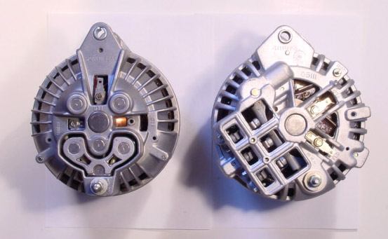
Below is an interesting variation. On the left is something I've never seen. It is a "roundback" which has been MADE from new to accept either grounded or insulated brushes. Again, here, a grounded brush is installed. On the right is the better design "squareback" which came out around 72? or so.

squareroundcomp.jpg


SO HERE IS the deal on all this. If you DO HAVE an alternator with TWO insulated field terminals, you need to pick one and permanently ground it for use with your 69 / earlier regulator.
 
The harness is simple. If the car runs, there is likely NOT a short. What you have is three wires

1....The output wire goes from the alternator, through the bulkhead, through the ammeter, back out the bulkhead to the battery.

2...The green field wire is one wire, and only has two ends. One end is the alternator field terminal, the other end is the VR field terminal (screw terminal)

3...The blue IGN terminal (push on terminal) is branched off from the "ignition run" circuit.

So if you jumper the blue and green together, you are running full 12V to the field / brush terminal. you can hook that up and check voltage at the field terminal.


It used to work fine but i started noticing the lights pulsing and i think thats where i took a ****! Ok, i have the 2 FLD from a 73 dart because there wasnt one locally and i figured if it would be ok with a extra unused FLD, if i need one just like my old one i will. I looked for the black wire coming off the bulkhead into the battery but there isnt one hooked to the GROUND(black). I can follow it in there but does it come out in another spot??? Can i ground to the black side of the battery from the extra FLD like previously stated because That is where i got the multimeter set to 20 volts to actually move up past 12.56V while running. Without that wire hooked up from FLD to ground(BLACK) i didnt get any readings.


Here are a couple pics. I tried to move the regulator off the wall and onto the fender.

https://www.flickr.com/photos/133376992@N02/sets/72157657106157943
 
OK. See the top field terminal? Permanently ground that

Your VR mounting ain't for squat. It needs to be GROUNDED. I don't know why you moved it? But wherever it's mounted, scrape clean around the bolt holes and flange and mount with star lock washers
 

Attachments

  • alternator.jpg
    95.7 KB · Views: 291
Nice pics and info.....


Thanks for nothing, i mean trying to pad your forum stats is cool too, but i assume you actually have something slightly intelligent to write at some point..............................
 
BTW that square back Alt puts out way more amps then your wiring and ammeter can handle at full output .

You should bypass the bulkhead connectors and run a 8 gauge wire with a maxi fuse near the battery directly to the alt from the battery.
Also add a maxi fuse near the bat and run to the ignition switch.

Not necessarily true. Just because it's a squareback does not mean 'really high' output. it could be in the neighborhood of 40-50A which is workable if the system is in good general shape.

I do agree, though that these old girls can be on thin ice

What he's referring to is "read this" LOL

http://www.madelectrical.com/electricaltech/amp-gauges.shtml
 
Thanks for nothing, i mean trying to pad your forum stats is cool too, but i assume you actually have something slightly intelligent to write at some point..............................

HEY! i am learning from this post also.... the PICS AND INFO are helping..... why would you start **** when i am LIKING the post... I have had the SAME issue with gauge pulsing and lights flashing for the past god knows how long.... this post has saved me from buying a new VR and now i know how to run down the issue.. thanks to the posts.... SO when someone posts that they like the info... they are benefiting from your post also... thats what a FORUM is about. Sorry i read the post and soaked up all YOUR information....
 
The harness is simple. If the car runs, there is likely NOT a short. What you have is three wires

1....The output wire goes from the alternator, through the bulkhead, through the ammeter, back out the bulkhead to the battery.

2...The green field wire is one wire, and only has two ends. One end is the alternator field terminal, the other end is the VR field terminal (screw terminal)

3...The blue IGN terminal (push on terminal) is branched off from the "ignition run" circuit.

So if you jumper the blue and green together, you are running full 12V to the field / brush terminal. you can hook that up and check voltage at the field terminal.

Now I'm baffled! I recently noticed that my headlights ( and maybe tail lights as well) pulse / flash on and off and can't figure out what to start checking! When I bought the car ( 69 Dart Swinger) it had this alternator in it, which looks like it's a 70, and charges high ( about 16 V) at higher RPM and goes down to about 14.5 at lower RPM. There are two "field" terminals on the back and the battery output, but wires only going to the output and the terminal at 12 o'clock. Is this wired wrong? What else should I be checking? The guy that I got the car from did a lot of pretty mickey mouse stuff so nothing surprises me!
 

Attachments

  • Dart alt.jpg
    46.9 KB · Views: 245
I replied in the other thread. Actually you should have started your own thread.

EDIT. For simplicity let's stay in the other thread
 
-
Back
Top