rmchrgr
Skate And Destroy
So I got some things done on the engine this weekend. The block was cleaned, painted and most of the freeze plugs have been installed.
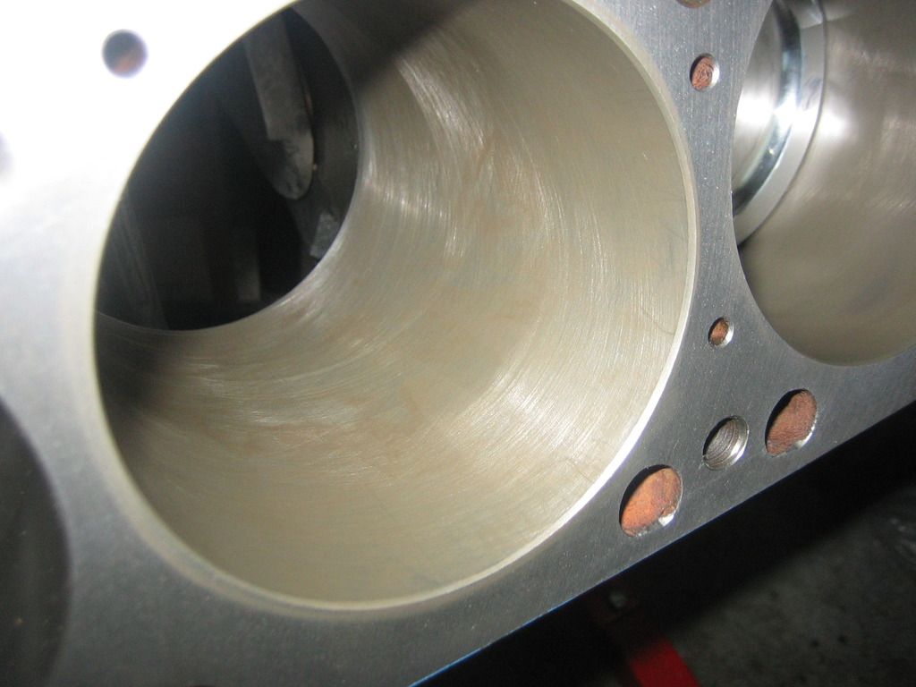
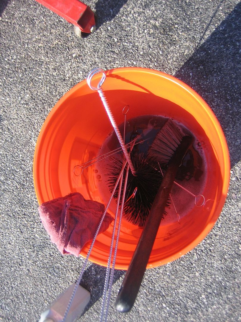
First step before any paint job is to clean. The block was hot tanked at the machine shop but it's still pretty dirty so it was time to put my fancy Moroso engine cleaning brushes to work. The set was around $30 and is worth it. There are several types of brushes for doing different jobs - cylinders, oil galleys, lifter bores, etc. Also went to HD and got a nice, clean 5 gallon bucket and a long-handle scrubbing brush for the outsides of the block. I used a cleaning solution of around 8 oz. of heavy duty Simple Green (purple) diluted into about a gallon and a half of hot water. Worked great! Block was cleaned and dried with compressed air, then the bores and cam bearings were oiled to prevent rust.
Here's the bucket of solution with the brushes.
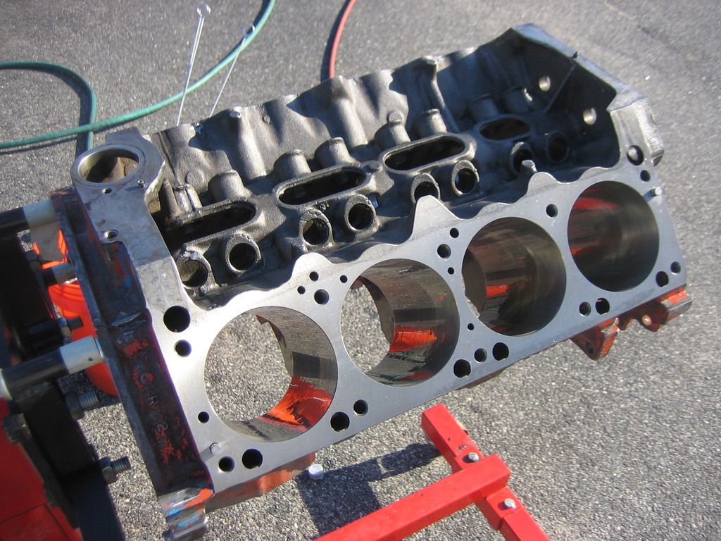
And here is the clean block. I had to re-do the masking after this. I used some older tape and it reacted with the soap and left a residue on the deck surface. I will have to get it off before final assembly. I used low-residue tape the next time to prevent that situation again.
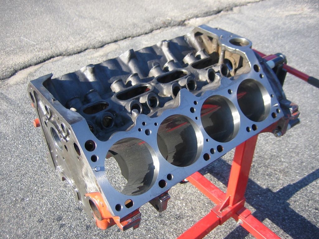
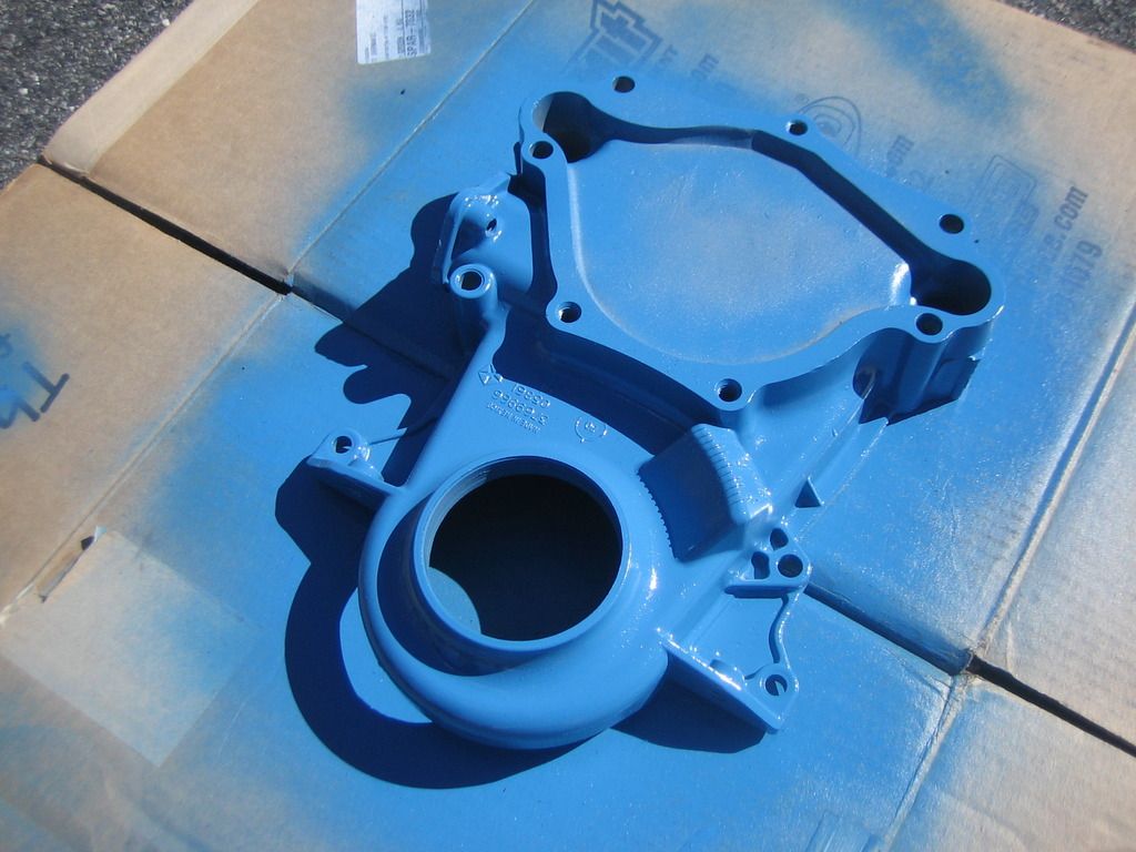
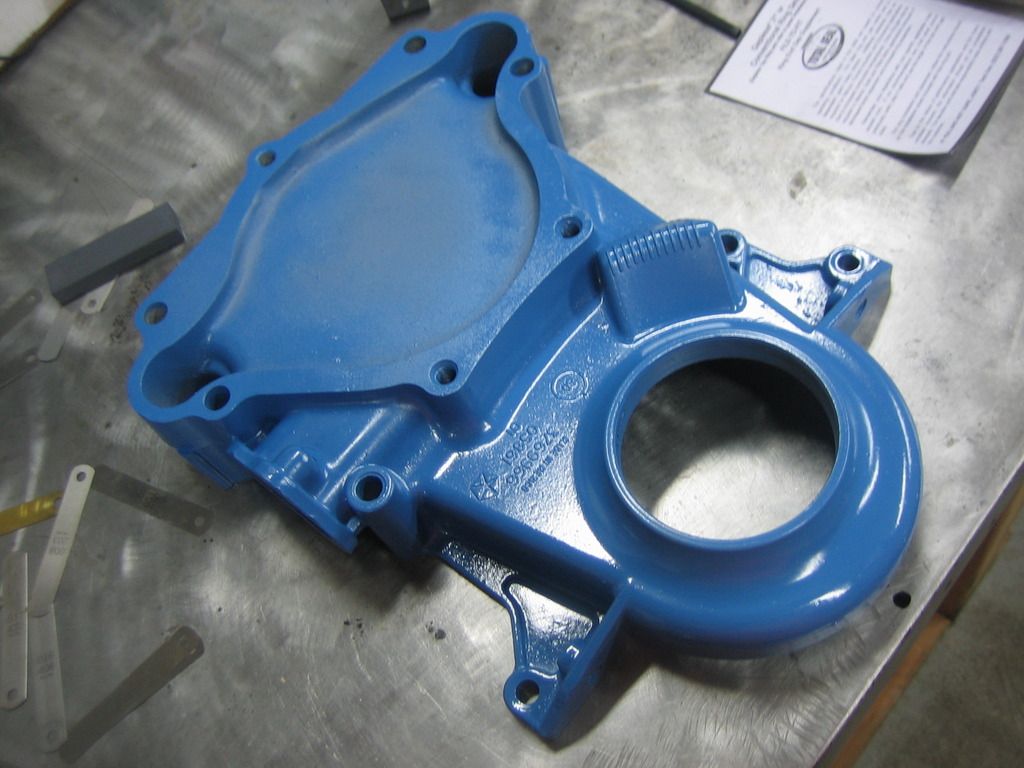
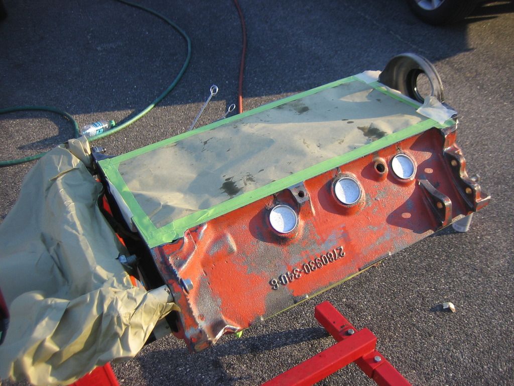
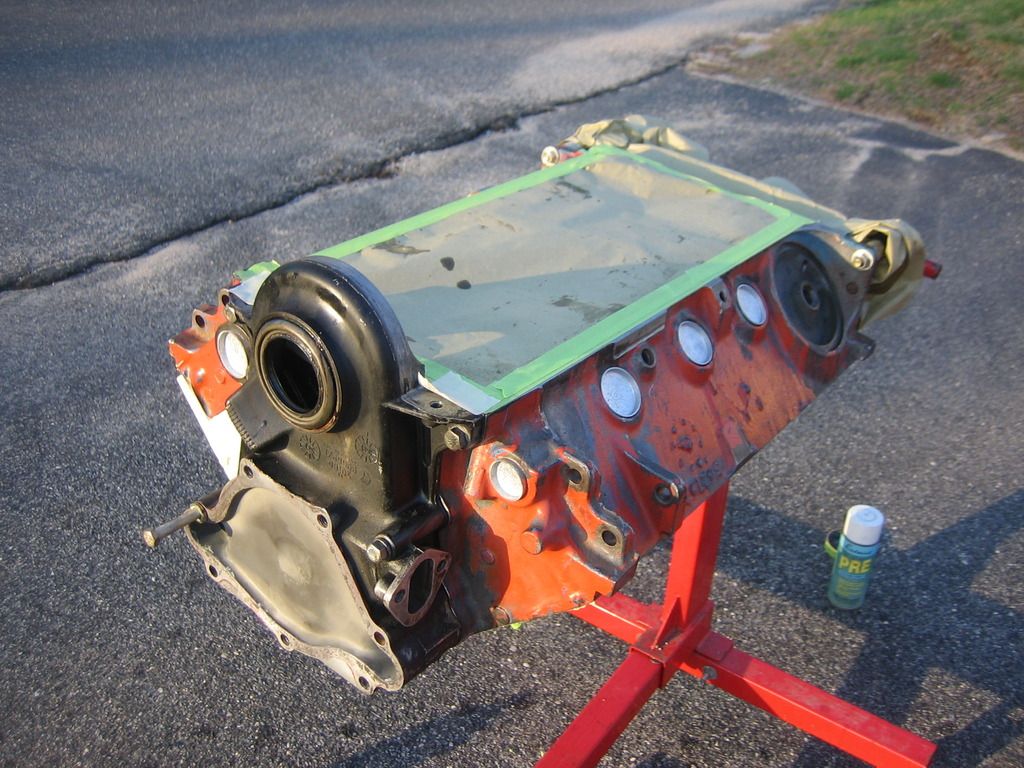
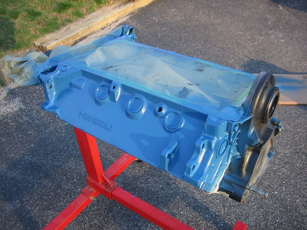
This is the freshly-cleaned block after the second masking job. I used an old timing cover to cover the machined surfaces on the front I did not want to be painted.
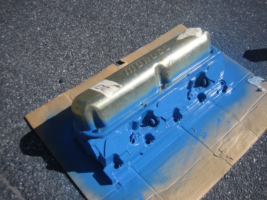
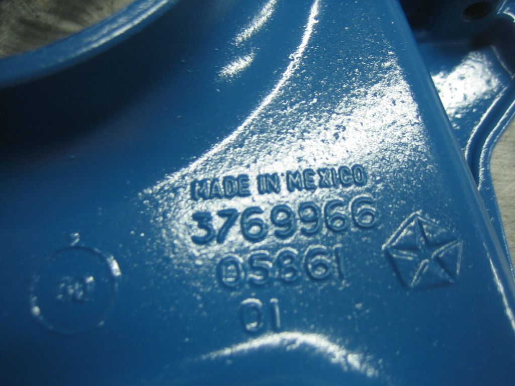
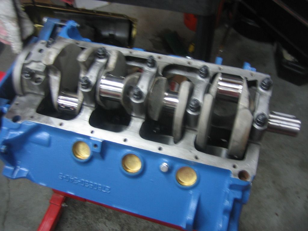
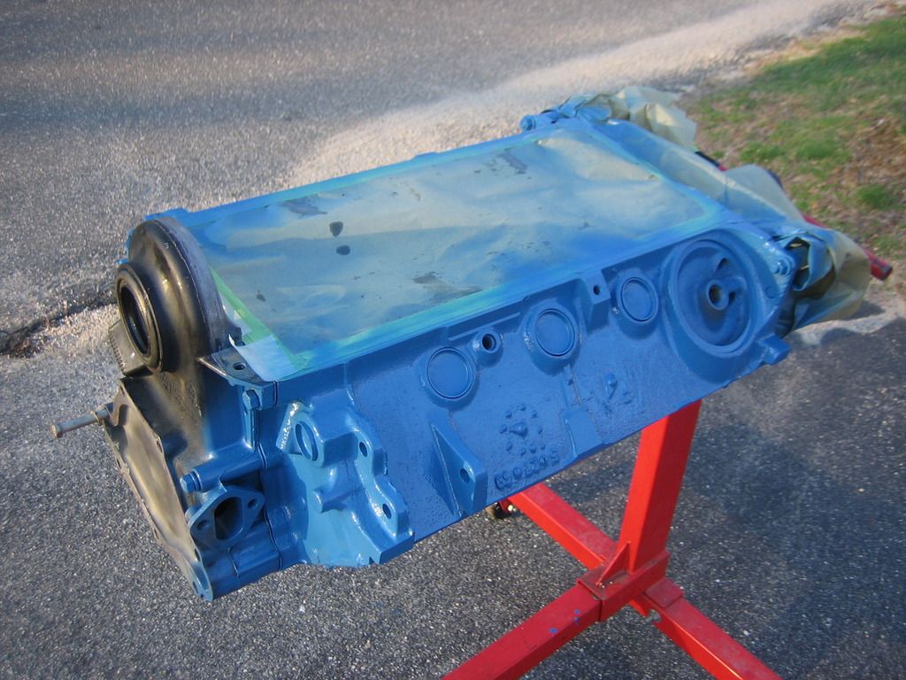
Chrysler small block blue! I love this color, it really pops. Incidentally, I used a set of steel freeze plugs that I had to cover the coolant holes during paint. I installed brass plugs but these were just to keep over spray to a minimum. Probably not necessary but that's the way I roll.
I put a second coat of paint on this morning and then put the freeze plugs in. I used Permatex "Indian Head" gasket shellac on the plug holes and sides of the plugs. You're supposed to wait until it dries but I just slathered it on and knocked 'em in. I can see why you should wait though because this stuff is really goopy and gets all over the place.
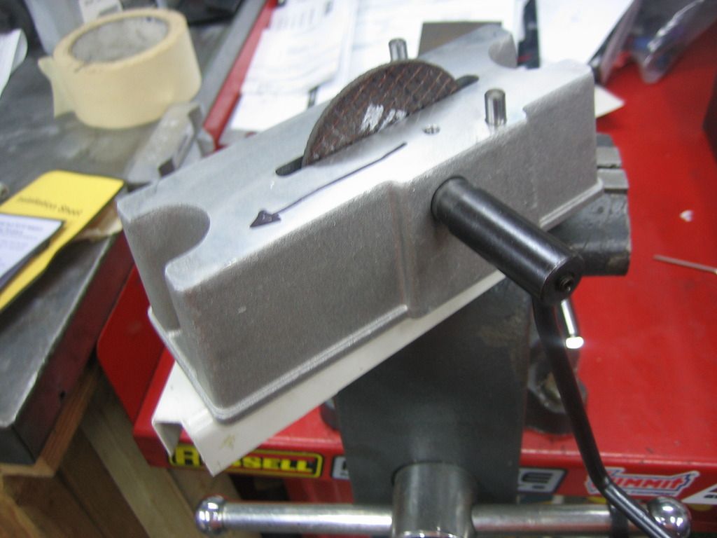
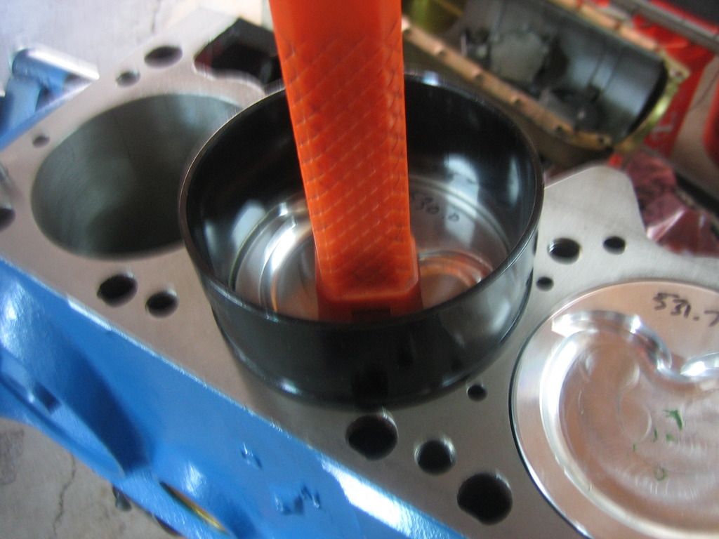
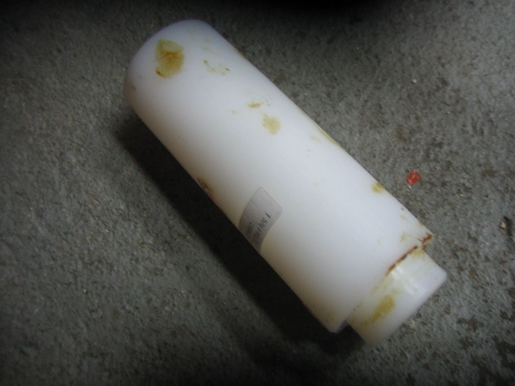
Since I am a guy that likes the right tool for the job, I used a cool freeze plug installer tool to drive the plugs home. Most guys use a socket or something that fits inside the plug to install them but this does not always work as well as it should for two reasons; 1) they need to go to a certain depth and 2) the plug can get cocked in the bore with a socket. The tool I used has a step that goes flush with the outside of the bore when the plug is at the proper depth which also makes it square. Works great! Smack it a few times with a hammer and it's in. Note residual goop on the tool, ignore sexual innuendo.
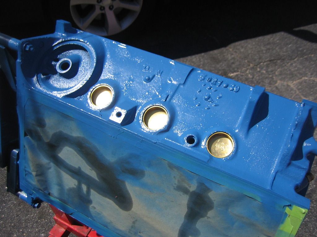
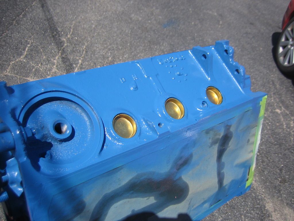
Here's the freeze plugs knocked in. I like the juxtaposition of the brass plugs against the bright blue, gives a nice detail.
I threaded a few plugs into the side of the block. Never sure exactly what these are for. I guess they are drain plugs? They are not pipe thread as far as I can tell so I didn't put any Teflon paste on them.
I also threaded in a dipstick fitting. There is a compression fitting with a ferrule that screws into this fitting so the dipstick is locked in place. I got it from Hughes Engines. I might get a cap for it and take the dipstick off between oil changes.
Last thing I did today was to paint the lifter valley with Glyptal insulating paint. There is always debate on whether to use this stuff or not. The claim is that it helps oil drain back and keeps the oil from penetrating into the pores of the cast iron. I really don't know myself but it seems like a good thing to me. My old engine had it and it looked fresh when I took it apart so I know it's heavy duty stuff. I believe it's primary use is to insulate electric motor housings that create a lot of heat. It's not cheap either. But I did it and it turned out OK. I wasted an old brush that I tossed after I was done with it. It was a little tricky not to get it into the lifter bores and on the deck surface so it looks a little unfinished in spots. It'll do the job just fine and it will be under the intake anyway.
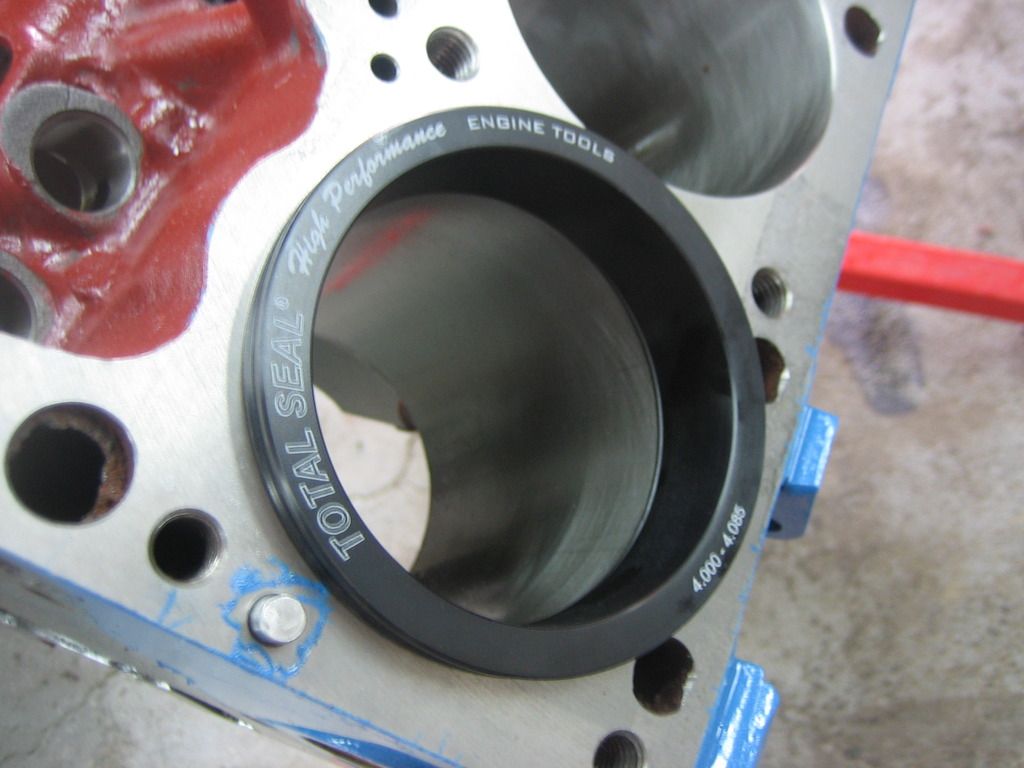
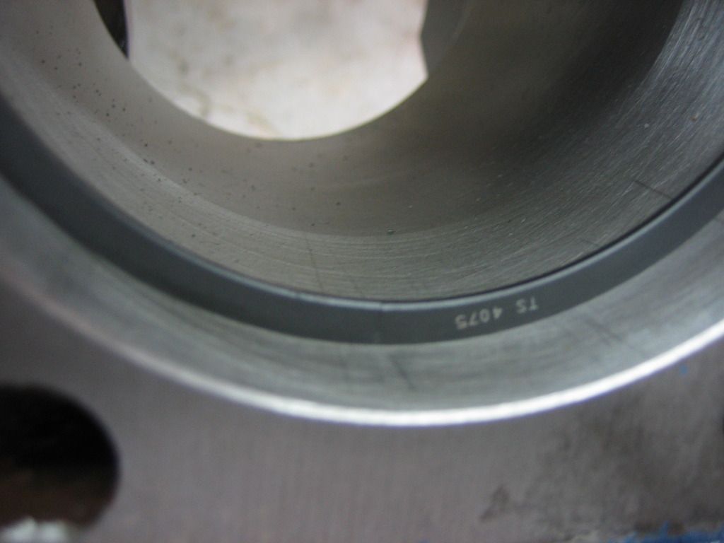
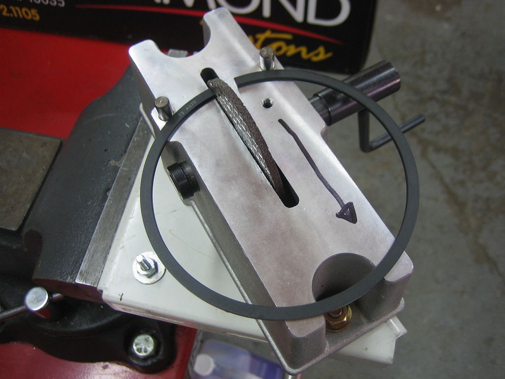
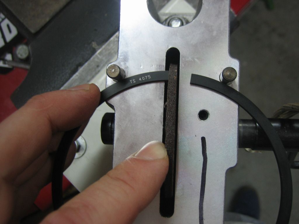
So the next step is probably to start file fitting the rings and install the rotating assembly. I plan to start as soon as time allows, hope to make some progress this week.
More to come!
First step before any paint job is to clean. The block was hot tanked at the machine shop but it's still pretty dirty so it was time to put my fancy Moroso engine cleaning brushes to work. The set was around $30 and is worth it. There are several types of brushes for doing different jobs - cylinders, oil galleys, lifter bores, etc. Also went to HD and got a nice, clean 5 gallon bucket and a long-handle scrubbing brush for the outsides of the block. I used a cleaning solution of around 8 oz. of heavy duty Simple Green (purple) diluted into about a gallon and a half of hot water. Worked great! Block was cleaned and dried with compressed air, then the bores and cam bearings were oiled to prevent rust.
Here's the bucket of solution with the brushes.
And here is the clean block. I had to re-do the masking after this. I used some older tape and it reacted with the soap and left a residue on the deck surface. I will have to get it off before final assembly. I used low-residue tape the next time to prevent that situation again.
This is the freshly-cleaned block after the second masking job. I used an old timing cover to cover the machined surfaces on the front I did not want to be painted.
Chrysler small block blue! I love this color, it really pops. Incidentally, I used a set of steel freeze plugs that I had to cover the coolant holes during paint. I installed brass plugs but these were just to keep over spray to a minimum. Probably not necessary but that's the way I roll.
I put a second coat of paint on this morning and then put the freeze plugs in. I used Permatex "Indian Head" gasket shellac on the plug holes and sides of the plugs. You're supposed to wait until it dries but I just slathered it on and knocked 'em in. I can see why you should wait though because this stuff is really goopy and gets all over the place.
Since I am a guy that likes the right tool for the job, I used a cool freeze plug installer tool to drive the plugs home. Most guys use a socket or something that fits inside the plug to install them but this does not always work as well as it should for two reasons; 1) they need to go to a certain depth and 2) the plug can get cocked in the bore with a socket. The tool I used has a step that goes flush with the outside of the bore when the plug is at the proper depth which also makes it square. Works great! Smack it a few times with a hammer and it's in. Note residual goop on the tool, ignore sexual innuendo.
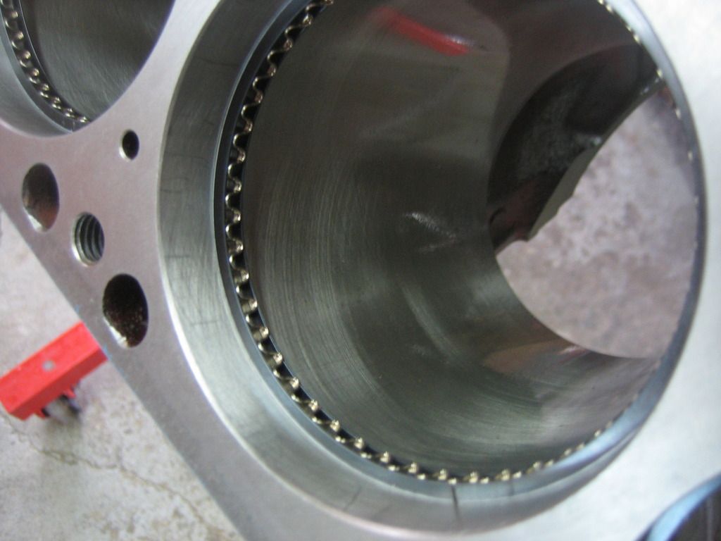
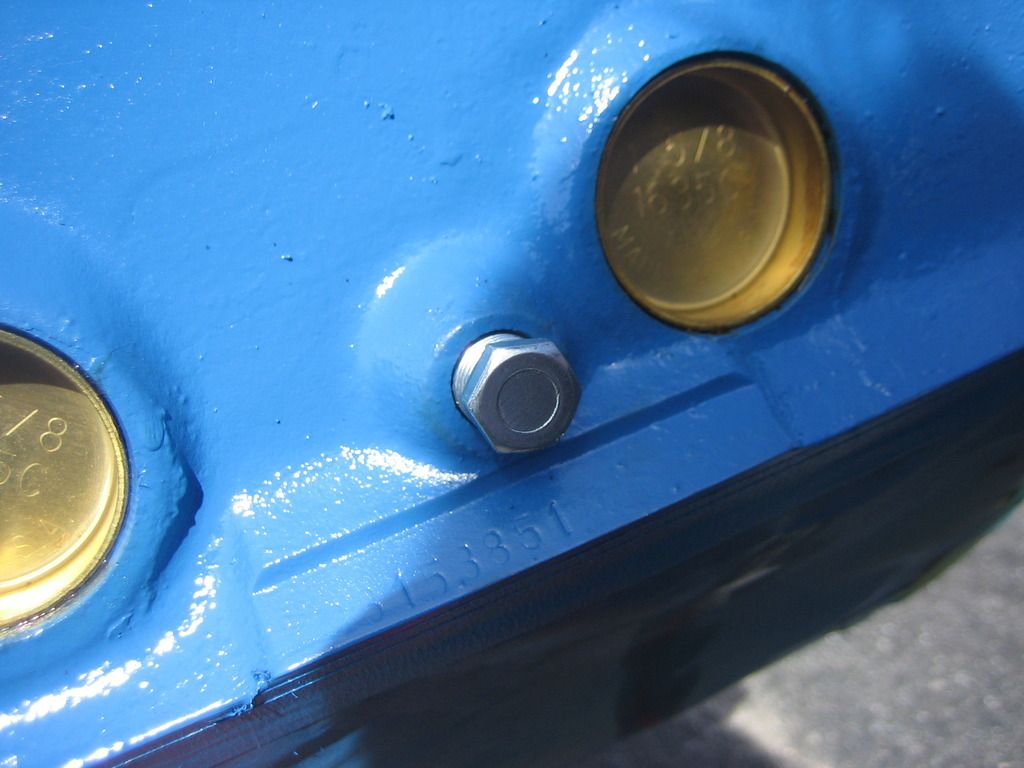
Here's the freeze plugs knocked in. I like the juxtaposition of the brass plugs against the bright blue, gives a nice detail.
I threaded a few plugs into the side of the block. Never sure exactly what these are for. I guess they are drain plugs? They are not pipe thread as far as I can tell so I didn't put any Teflon paste on them.
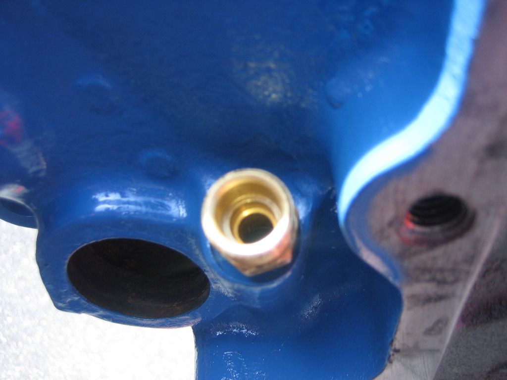
I also threaded in a dipstick fitting. There is a compression fitting with a ferrule that screws into this fitting so the dipstick is locked in place. I got it from Hughes Engines. I might get a cap for it and take the dipstick off between oil changes.
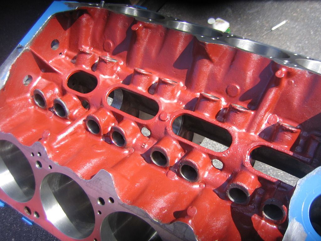
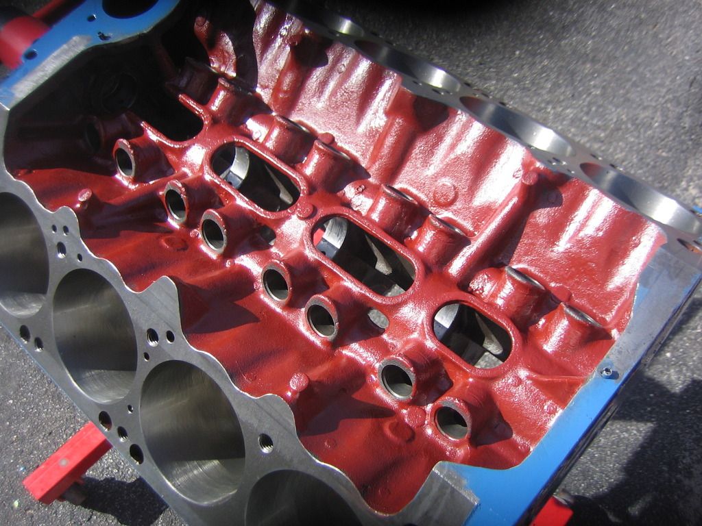
Last thing I did today was to paint the lifter valley with Glyptal insulating paint. There is always debate on whether to use this stuff or not. The claim is that it helps oil drain back and keeps the oil from penetrating into the pores of the cast iron. I really don't know myself but it seems like a good thing to me. My old engine had it and it looked fresh when I took it apart so I know it's heavy duty stuff. I believe it's primary use is to insulate electric motor housings that create a lot of heat. It's not cheap either. But I did it and it turned out OK. I wasted an old brush that I tossed after I was done with it. It was a little tricky not to get it into the lifter bores and on the deck surface so it looks a little unfinished in spots. It'll do the job just fine and it will be under the intake anyway.
So the next step is probably to start file fitting the rings and install the rotating assembly. I plan to start as soon as time allows, hope to make some progress this week.
More to come!