(This post is pretty basic and most on a US forum will know where the various sensors are located and their function. The part #s and other info may come in useful however.........)
PART #s
- Any sender block with 1/8-27 NPT thread fitting
- Any NPT adapter bung converting block thread to 1/8-27
- Factory 5.7 Cam sensor 56041584AF
- Factory 5.7 Crank sensor 56028815AA
Various sensors need to be changed to suit both the
MSD 6013 ECUand
MSD 88863 wiring harness, and the 1971 Chrysler instrumentation.
Cam and Crank
The 06-08
MSD harness 88863 requires the use of the 05-09 5.7 cam and crank sensor.
This is the reason why MSD claim the ECU won’t work with the 6.1. It’s not the functionality of the unit, simply that the harness is supplied with the 5.7 style plug clips for these two sensors..not the 6.1 style which are much smaller.
The solution is simple .......The MY 5.7 05-08 sensors screw straight in to the 6.1 block.
I bought mine from
www.eastcoastmoparts.com shipped and arrived in 8 days.
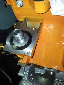
The Cam sensor is located in the front timing accessories cover just behind the water pump outlet.
The Crank sensor is located at the side of the block on the left side (as you face the car) towards the rear.
Both sensors are O ringed and secured with one screw.
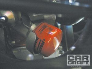
Oil
The 3G Hemi is fitted with both an oil pressure switch and an oil temp switch. They are poisioned directly above the oil filter boss.
The Oil temp switch screws in to the top oil auxiliary port. I’m using this port for my return oil line from my remote filter so won't be using an oil temp switch.
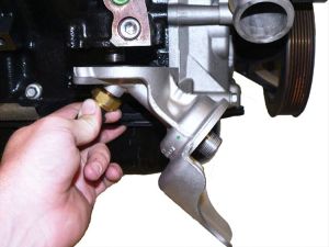
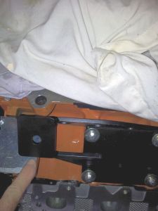
The oil pressure switch screws into the front of the block.
The oil pressure switch utilises the same thread as the LA small block oil switch!!
.....so you can simply discard the 6.1 sensor and fit whatever variation of oil pressure switch or line you want to use.
I’m using a splitter block so I can run the factory oil light and my aftermarket DIXCO oil pressure gauge..to stay with the old school interior.
Water temp
The water temp switch is located at the top right front of the block (facing the front of the car) – and is a completely different thread from the LA small block temp sender. You will need to buy an adapter bung. Mine cost $2.98!
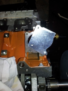
MAP sensor
Although the MSD 6013 ECU is primarily a spark controller – it does allow you to use the manifold air pressure (MAP) sensor to plot the manifold pressure to modify ignition timing at low and high vacuum.
The EFI intake MAP sensor is located at the rear of the intake. It is secured by an o ring and two screws. I simply removed it and attached it to the Indy Modman as this intake has a provision for this sensor.
These are the only sensor modifications required as I am not running EFI and am not using a fuel controller of any sort.....except the carb!
 rotest:


")