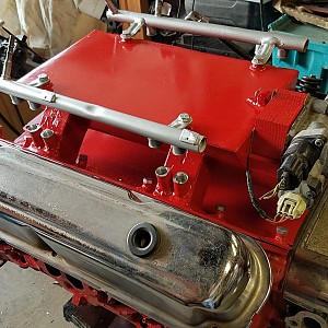
This was a proof of concept MPEFI intake I fabbed up for a turbocharger I am planning to install. The runners are not the best match for the ports but are very close to what I needed. The next one I will build will have thinner walled rectangle tube runners or more likely 1.75 inch EMT runners that are formed to the port shape at the flange. The flanges were cut with a combination of plasma, jig and bandsaw, depending on when I cut them. I started with a plasma but the cuts were nasty and then the consumables wore out. I then used a 24 tpi jig saw but it was agonizingly slow, maybe an inch a minute! I finally cried uncle and bought a bandsaw to do the heavy cutting of all walls and used the jig to cut the remainder of the ports with a 1/2 drill used to make the corner cuts and the jig to cut the sides out of each port. I then used a die grinder and a carbide cutter to manually shape the ports to what the intake manifold gasket would seal to. They turned out kinda rough but they will seal. I purchased the rectangle tube at a metal supply shop as heavy walled but they do have lighter walled that has an increased ID but since this will be forced induction, I thought the slightly smaller runners would not be an issue. I welded 2 together for 4 sets of runners. I then tacked them up to see where the overlap would be and where the walls of the plenum would intersect and marked them so they would sit flush in the plenum. This is not ideal as there is dead air on the walls of any plenum but I did not have any radiused intake plans so I cheated a little and made them stand off a few mm, this would serve a second purpose later. After I mocked up the plenum box with cardboard, I cut the parts out of 1/8 plate (all material is 1/8, try and use 1/4 for flanges) and tacked up the box except the top. After a few cuts to clear the runners, I welded it all together and used seam sealer to cover all the internal seams. There are probably better choices than seam sealer but this was inexpensive and we all know how hard this stuff gets. I just wanted a fairly airtight box, so I hit all the seams from the inside. The outside fit was pretty good so I only had to use 2 part epoxy to fill a few small gaps, and I ended up using 10 minute epoxy on a number of things. Mostly where a flux weld was that was all bumpy and bird crap looking I just lopped some epoxy on it and it would smooth it out considerably for final paint as seen on all the bolt bosses and bungs. For the bungs, I initially was going to drill 3/4 holes in the runners and sink the bungs into the runners and epoxy set them then grind out the internal runner slag so it was smooth. After finding my 3/4 bit was toasted (and it is pretty hard to drill into these runners with a hand drill, I decided to do the next best thing. I drilled smaller holes and cut the bungs at an angle to they would sit over the holes but have the runner as support when you are pushing the injectors into the bungs. You wouldnt want one to break the epoxy bond and push into the runner! This worked very good as the cone spray pattern of the single hole Magnum injector is pretty small. After I cut the injectors to sit at the correct angle, I used the Magnum fuel rail to find where the injectors would sit in the runner pairs. My first bungs were centered, but I found the centerline of the fuel rails were farther apart than the runner by about 2 mm on each side. In the next version I will make the runners wider and mount the injectors higher up so they will be centered in the runner. I made a new set of bungs with an offset pocket so I could get the injectors to seat at a minimal angle and it worked pretty good. So after all the bungs were epoxied on and the fuel rail was fitted, I finished sealing the runners with epoxy along the raised edge and welded the top on. Now it looks like an intake. now you have to decide what TB youll be using. I ended up using one from a jeep as it has the IAC integrated into the TB and it also has a round shape. So many have an oval shape that would be difficult to work a boot onto unless its the factory piece. Bad thing about it was that it was physically taller than my plenum so I have to make an adapter out of marine plywood so I could divert the IAC passage down into the plenum. I did this by drilling a hole at a diagonal in the 4" thick wood adapter to bring the idle port inline with the plenum. Drilling out the 66mm hole in the end while it was assembled was a bitch so try and do this before you weld it up. After that I cut and bent the fuel rail tabs so it would attach to the top of the plenum onto nuts I tack welded on. It worked out nice. Even if the plenum is not 100% airtight, being a bleed type idle (IAC is a variable leak) makes it work as it can vary the air it needs to maintain the idle. What I learned on this first run was that the runners will be different next time. I will either use 2" square runners and cut them at an angle lengthwise and weld them back up to make a tapered runner or make them out of 1.75 EMT and have them angle in toward the ports. This will also allow me to cut 1.75 holes in the plenum wall with a hole saw to make a nice entry. I will also use 3/16 or 1/4 for the flanges as the 1/8 is pretty thin. How will it run? Dont know, but it should at least run and take a turbo inlet and still fit under the hood. Some are out of order, but you get the idea. Took me 3 months to finish this, working off and on with tool purchase and modifications to band saw, but could probably do another over a weekend if I had the materials now that I know what I need to do.![]()
![]()
![]()
![]()
![]()
![]()
![]()
![]()
![]()
![]()
![]()
![]()
![]()
![]()
![]()
![]()
![]()
![]()
![]()
![]()
![]()
![]()
![]()
User Comments
Sort Comments By