360 engine pictures

-
No probs. I must be looking in the wrong areas..i would not have thought that this information would be difficult to find. Thankfully, it is not holding the build up at the moment but it will be soon. I need to paint and it is going to rain for a few more days...

ian.

Do you need a pic of brackets installed, uninstalled, or both? Here is what I have at the moment. Not sure if this helps
 

Attachments

  • image-375370980.jpg
    98.1 KB · Views: 236
  • image-445026996.jpg
    82.4 KB · Views: 215
  • image-1964853410.jpg
    79.2 KB · Views: 214
Fuel pump Bolts are 5/16 18 bolts About 1 1/2 inches long
 

Attachments

  • engine1.jpg
    69.9 KB · Views: 229
  • 52012 070.jpg
    64.8 KB · Views: 235
  • engine.jpg
    76.5 KB · Views: 232
Sorry about sounding dense. I am a visual learner.

Mopardaddy and dwire67..big thanks for the pics...and mopardaddy for the bolt information. They will go on my list to buy.

Some random questions:

I thought there were only 3 "pulleys" but now that I see it I now understand where my moroso pulley comes into play..and I need 4. My 'main" pulley only has one v groove on it. Could I be only using one fan belt ? I checked with the pulley I took off the /6. It only has one groove well. Do I need 2 ?

The alternator brackets bolt into the water pump assembley.

The power pump brackets look different on both engines. Do mine brackes earlier in this thread look right ? I have another set on a spare..here is a bad pic..

_IGP8186a-XL.jpg


If I were a betting person, I would say that this looks better and clears up some confiusion as well. It also connects to the water pump bolts.

Does the fan bolt directly on the water pump or is there an attachment fbetween the pump and the fan ?

I appreciate the help.

Ian.
 
Moroso pulley , it is a crank pulley or alternator? I can give you this advise... Do not use a Moroso pulley on the street at all. Nothing but problems because they slow down the belt speed. Your power steering pump looks like it off a newer vehicle, what fan do you have a Direct mount fan or one with clutch?
 
Dwire,

No...I checked, it is the same power steering pump (not sure if works) but with a completely different bracket to attach on the engine. I can more that bracket over to the other pump.

I bought the Moroso pulley for exactly that reason...it frees up a bunch of HPs in the engine. It attaches I believe to the harmonic balancer. I was going to convert my Mustang to under pulleys but bought the Duster instead :) Will the slower RPM affect the cooling or alternator ?

This is my fan..

fan-L.jpg


So I am going to have some sort of pulley on it.

Think we are getting closer to a solution.

Ian.
 
Dwire,

No...I checked, it is the same power steering pump (not sure if works) but with a completely different bracket to attach on the engine. I can more that bracket over to the other pump.

I bought the Moroso pulley for exactly that reason...it frees up a bunch of HPs in the engine. It attaches I believe to the harmonic balancer. I was going to convert my Mustang to under pulleys but bought the Duster instead :) Will the slower RPM affect the cooling or alternator ?

This is my fan..

So I am going to have some sort of pulley on it.

Think we are getting closer to a solution.

Ian.

The fan will bolt to the water pump pulley. You may have already known that though. Ignore if that's the case lol
 
dwire..

It is raining too hard to be out in the garage today but I will take the power steering pump and see if I can mate it to the water pump bolts.

Can I get away with one belt or do I need 2 ?

Ian
 
Ok...so this is the solution for the power steering pump..spent some time playing with it..

The holes that correspond to the water pump holes are circled in green.

Front

psp1-L.jpg


Rear

psp2-XL.jpg


Now I just have to figure out if I need one or two main pulleys.

ian.
 
Thanks guys..

I was just told today (by my local tool rental guy) to run the alt or alt and fan together only...not to combine the power steering pump on the came fan belt..I see that Abodyjoe and dwire do this. I have a single groove pulley for the fan so I will sell this pulley (moroso) and buy another..thanks for the info on to where to source..was my next question :)

Another step forward today. Feels good. Thank-you.

Now if it would stop raining...

Ian.


Yes, you should run one belt to the fan, alternator, and crankshaft. Then a seperate belt for the p/s pump from the crank.
 
I gave my 2 groove pulley away when I gave my drive train away earlier this anything.....

Ian.
 
Just in case you haven't figured out what to do with these intake holes:

View attachment Intake plumbing.jpg

#1. Is for the heater hose nipple. If I remember correctly a 3/8 pipe thread, be sure to match the nipple to the heater hose outlet, either 1/2" or 5/8" so you don't have to use an adapter. Mancini also carries nipples for these.

#2. Is for the temp sensor, but looks a little big and may need a reducer bushing. This looks like a 3/8 pipe thread, but the temp sensor is a 1/4 pipe thread. You will need a reducer bushing to go from 3/8 pipe thread to 1/4 pipe thread.

#3. I would plug it.

#4. I would plug it.

#5. I would run the bushing for a manual temperature gage or if not plug it.


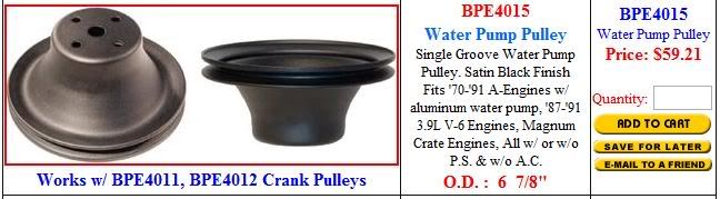
Also pay attention to the big hole in the front of the intake. There were 2 different sizes of bypass hose used there. Match the one with the water pump that you are going to use. They used one size in the 60's for the cast iron water pump, and changed them when they went to the aluminum water pump in I believe it was 1970.


Let me give you some insight on pipe threads. There are two types of pipe thread, straight pipe thread, and tapered pipe thread.

If you need to tap a hole for pipe thread, you should use STRAIGHT pipe thread. This way the hole is consistent all the way through. If you use a TAPERED (wedge shaped) pipe thread, you have to be VERY CAREFUL not to tap it too deep, or your hole may get opened up too big and your part may want to go deeper than the tapped hole. If you have to tap a hole with a tapered pipe tap, go down some, then test the part that you will put in it. If it is too tight, then tap a couple more threads deep and try it again. Keep going one or two threads until you get it right. If you go too deep, you will have too big of a hole and will be difficult to fix.

The Chrysler standard is to use a STRAIGHT pipe thread for the female (hole) thread and use a TAPERED pipe thread for the male (plug/wedge). This way, the male thread will "wedge" into the straight pipe thread hole and seal better like a cork. The threads are compatible enough for this to work.

Most hareware stores only stock tapered pipe taps. You should try a Production Tool Supply store, Grainger store, or last resort a tool truck to find a straight pipe thread tap.

And for whoever posted the picture originally, I hope I did not violate any copyright by using your picture (ha,ha). It was a good picture with all of the holes referenced.

I hope this helps some of you out.
 
I gave my 2 groove pulley away when I gave my drive train away earlier this anything.....

Ian.

Mancini Racing carries brand new pulleys. You can order one from them.

They also carry brand new alternator bracket set ups if you need them also.
 
Krazykuda....that information is great. I hadn't realized the difference with the tapping..i thought they were all the same. I am using some aftermarket gauges (including temp). Haven't got that far to test fit. I hadn't realized that Mancini carries these..I have them bookmarked :)

Still learning and thank-you.
Ian.


You're welcome. I became somewhat of a "thread expert" with my years as an engineer in the automotive industry. It started when I was building my cars and engines myself in high school and had to learn how to use a Heli-coil thanks to junk Craftsman taps. When I was in the auto industry I kept learning as much about threads as I could.

I had a project where I had a 120 mm diameter (approximately 5") thread where the two pieces wouldn't fit together. I had to go to a special precision measuring shop that could measure within one millionth of an inch to prove which thread was incorrect so we could get the parts fixed. They had to use the "three wire" method of measuring where they used three pieces of wire set on the threads and measured across them to determing the exact pitch of the threads. It was mind-boggling!

I learned how to measure the inside threads (minor diameter) to determine which drill bit to use to drill before I tapped a hole. Very useful when working on cars as a hobby.
 
Krazykuda....that information is great. I hadn't realized the difference with the tapping..i thought they were all the same. I am using some aftermarket gauges (including temp). Haven't got that far to test fit. I hadn't realized that Mancini carries these..I have them bookmarked :)

Still learning and thank-you.
Ian.


Yeah, the stock temperature sensor goes into the hole #1 in the pucture, then you can use hole #5 for the atermarket gage as this is close to the thermostat and will give a good reading. You have to be careful how deep you install the bushing that the temperature gage sensor goes into bacause if it gets threaded too deep the temp sensor at the end of the "wire" will bottom out on the bottom of the intake. If that happens, you can put another bushing in line to raise it up.

You also thread the mechanlcal oil pressure gage into the stock hole for the stock oil pressure gage (where the original oil sending unit goes). You won't be able to use your stock oil pressure gage in the factory gage cluster as there is not much room to put a "splitter" in there and run both. You have to take into account that it is near the firewall and the engine will move when put under load and it may cause the "splitter" to hit the firewall and eventually cause a leak. The oil pressure hole that you use is the one next to the distributor hole.

Also keep in mind with a mechanical oil pressure gage, DO NOT USE THE COPPER TUBING LINE! Copper tubing "work hardens" with bending/engine vibration and will eventually cause a crack in the line. Use the nylon tubing that comes with the gage kit. I also recommend to buy an extra nylon tubing kit (Mancini also stocks them) and throw it in your glove box. I had an incident in my 68 Cuda where my line sprung a leak and I was like 10 miles from home and oil was shooting all over my carpet (luckily it was black). I didn't have a spare line, but I would start the engine and get up to speed, then shut it off and coast to the next stop light. Then when I got the green, start it up and get to speed and shut it down. I was able to make it home that way without running dry on oil. Since then, I always carry a spare line in the glove box.

Another tip for when you install the gages. Go to the fuse block under the driver's side and use the orange wires coming off of the fuse block to hook up the gage lights. This is the circuit that runs the gage lights. Then your gage lights will come on and dim with the dash lights. I use a "piggyback" fitting and stack it onto the stock wiring. That way I don't have to cut into the stock harness and I can remove it if I need to later without any signs that it was ever there. Easy install and uninstall. It is also the same orange wire that goes to the factory radio. But I find it is easier to run the wire from the fuse block with the piggyback than try to splice or use a flat terminal into the radio connector.
 
Krazykuda....that information is great. I hadn't realized the difference with the tapping..

Still learning and thank-you.
Ian.

I had to support two engine block machining lines in my career. That is how they ran the pipe threads for the drain plugs in the engine blocks. It makes sense to use the straight pipe taps for the hole and a tapered pipe thread for the "plug". Then you get the wedge/cork effect to seal the hole from leaking.
 
Krazykuda,

I had to look some of what you mentioned up but I understand (most of it).

I will be using electronic guages when I can. I have seen the results of a failed mechanical ones.

I am just now trying to understand the wiring behind the cluster..I appreciate the tip on the orange wire. I am replacing the existing cluster with a design of my own with a lot more usable information.

I bought a gizmo today that lets me size out a nut size for a bolt...can I use the template in reverse to size out the proper bolt for the hole ? O ne of the issues I am running into is not enough bolts...

Do you have a service manual for your car?

My experience is with the 67 -68 Barracudas and 69 Valiant. The lights for the gauges and radio lights usually has orange wires that come off of the fuse block and go to the radio and gage cluster. If you use that wire, the gauge lights will come on when you turn on the lights and also will dim and brighten with the dimmer switch for the dash lights (it's cool when you can keep them all dimming together).

I'm not quite sure what you are referencing when talking about a template for nut/bolt size. Bolts and nuts are classified by their outside thread diameter and pitch (# of threads per inch). They have a coarse pitch and a fine pitch. Most of the bolts used on these cars are coarse, but you will find a fine thread once in a while. It is pretty easy to measure the outside diameter of a bolt with a set of vernier calipers, or a rough estimate by putting up to a scale/ruler. If you have a nut with a known pitch and diameter, yes, it can be used to figure out which thread is which.

Bolt length is determined by measuring from UNDER the head of the bolt to the tip of the bolt. Typical coarse threads are like 1/4 x 20, 5/16 x 18, 3/8 x 16, 7/16 x 14. Once you determine the thread for a bolt, then you need to determine the length needed. That is the measurement from under the head of the bolt to the tip of the threads.

Another way to determine the length of a bolt needed is to measure the thickness of what you are trying to secure. Typical thread engagement (the amount of thread you need to hold properly) is 1 1/2 times the diameter of the thread or the (thread diameter x 1.5).

So for a 1/4" diameter thread, you should have at least 3/8" engaged thread depth. For a 5/16" diameter bolt, you should have about 1/2" engaged thread depth. For a 3/8" bolt, you should have roughly minimum of 9/16: of engaged thread depth. For a 7/16 thread, you should have just over 5/8" minimum thread engagement. For a 1/2" thread, you should have at least 3/4" engaged thread depth. For anything under 1/4", you should be able to use 1/4" to 5/16" of thread engagement.

I hope this helps you. If you have any more questions, let me know. If you don't understand something, describe where you are confused, and I will try to explain it another way to help you understand. I don't mind explaining it different ways, and there is no "dumb" questions. I've been doing this for over 32 years. I'm sure there are many things for people new to the hobby to learn and understand. There are also lots of things that I don't know, that other people here do. That is what makes this a good place for information.
 
First thing I bought after we got the car :)

The template is like a fixed caliper...it is made of plastic or metal....it is a rectangle with ever increasing size holes drilled in it....you take a bolt and find a hole that fits...then you know what size nut to use. I was just pondering if I layed the template over a hole, would it give me the bolt size...what it wouldn't account for the thread size..and most of what I have seen around the duster is course.

The other information you provided on bolt length is very informative. I am now starting to buy bolts and size (length) is important.

Thanks
Ian.
 
I wouldn't rely on that template to measure the hole size. The template is designed to fit a bolt through and measure the OUTSIDE DIAMETER of the threads. When you look into the threaded hole, you see the INSIDE DIAMETER for the threads which is quite a bit smaller.

I think that you would be better off going to a hardware store and buying one of each of the threads 1/4" through 1/2" in coarse thread (like 1/2" to 1" length) and the matching nuts. Make sure to label each one and put it in its own bag with the proper bolt and nut thread: 1/4" x 20, 5/16" x 18, 3/8" x 16, 7/16" x 14, and 1/2" x 13. Then try to thread them in each hole in question at least three threads to make sure it is the proper thread. It should not bind in the hole if the threads in the hole are clean and no dirt gets in the threads. Then mark down on a sheet of paper what you determine to be the thread size and go from there.

Or if you need, tell me what part you are looking at, and I can tell you the thread. example:

All the valve cover bolts in the head are 1/4 x 20" thread and about 3/4" length.

The head bolts to the block are 1/2" x 13 - Buy a head bolt kit

The holes in the front of the block for the timing chain and water pump are 3/8" x 16 and vary in length depending on which hole they go in.

The holes for the rocker arms are 5/16" x 18 and you need the proper factory bolts for the shim/washer for the shafts.

The holes in the head for the exhaust manifolds are 5/16" x 18 and length depends on what manifolds/headers you run.

The holes in the head (I said holes in the head, ha, ha) for the intake are 3/8" x 16 and should be 1 1/4" to 1 1/2" length.

The holes in the block for the oil pan are 5/16" x 18 and should be 3/4" to 1" long.


I can give more later, I have to get ready to go to the Fleetwood Mac concert.

if you are building a 360 with the alunimum water pump, I can give you the bolt dimensions when I get back. I just did this for my son's block and can look at the bolts and give you the dimensions.

See you after midnight tonight.
 
-
Back
Top