67 Cuda 273 Alternator Upgrade Questions

-

goomasterc

Well-Known Member
Joined
Mar 2, 2012
Messages
46
Reaction score
0
Location
Saline
I've had other posts about tapping into some ignition run circuits and adding a car stereo with great response. The summary of that activity was that I need to upgrade my alternator!

What needs to go along with an alternator upgrade (100A or such). Voltage regulator as well? I'm an electrical guy, but not an electrical CAR guy. I understand that the wire between the systems has to be able to handle the load, I'm just not sure about everything in between. What all is affected??

I've also been advised about making changes to the Ammeter gauge.

Thanks all.
 
The first question you need to answer is how much more amperage do you need for your car stereo? 100 amps may be overkill.
 
To upgrade your alternator is a rather simple process. First, you should try to find an old underhood wiring harness from a 72 or later car with electronic ignition and snip the voltage regulator pigtail from the harness to splice into your existing harness. Then get yourself a squareback, dual field alternator of the required amperage and the newer style voltage regulator. The squareback may also need a different belt as some of the adjustment of the belt is lost changing from the old roundback. Then replace the old voltage regulator with the new style and splice in the pigtail you got from the donor. The wires are the same colorso this is a no-brainer. Then all you need to do is run a 2nd field wire from the 2nd terminal on the new alternator and run it back to the new voltage reg and splice that into the blue wire. The green wire at the regulator is already the first field wire.

Thats it, easy peezy!! Now you're ready for increased power output and also in case you change from points to electronic, if you haven't done that already!! Good luck with the project, Geof
 
I don't want to sound too hard on Geof, but


To upgrade your alternator is a rather simple process.

Maybe, maybe not. READ please this MAD article about the pitfalls of bulkhead connectors that are in poor shape, along with other problems in the harness caused by 40 years of detriment

http://www.madelectrical.com/electricaltech/amp-gauges.shtml

Generally, the problems are:

Deteriorated bulkhead connector terminals

Too small wire for a substantially larger alternator, especially when coupled with lots of add ons, like electric fans, pumps, big stereos, modern headlights. This has been bandied about previously, but there is evidence that "fleet" cars (police/ taxies) used modified alternator wiring, that is, larger wiring fed through the bulkhead separately, for larger alternator installations.

Problems right at or in the ammeter---the ammeter can corrode internally. The studs of the ammeter are not brazed to the internal guts (shunt) but are "almost" rivited, and rely on the nuts for electrical connection. The melted ones shown in MAD article actually are victims of later model PLASTIC cluster castings.

Problems in rare cases with the "in harness" (welded splice) shown in the simplified MAD diagram


find an old underhood wiring harness from a 72 or later car with electronic ignition and snip the voltage regulator pigtail from the harness to splice into your existing harness

You don't have to get that carried away. You can buy new regulator pigtails from some parts stores


Then get yourself a squareback, dual field alternator of the required amperage and the newer style voltage regulator.

This IS substantially true, and there are other (off brand) alternators some guys like, as well. Properly, these are not "dual field" they are "isolated field." They have dual field CONNECTIONS, not "dual fields"


Thats it, easy peezy!!

So it may NOT be all that eezy peezy


So in conclusion, PLEASE CAREFULLY read that MAD article. If you do not decide to perform the ammeter bypass, at least examine carefully the factory wiring AND THE bulkhead connector.

Don't go hugely overboard on your alternator. Something in the 45-55A range should run a "normal" car just fine. Getting up in the 60A and larger units may start to cause problems with your old wiring. The above mentioned "square back" units like this:

PaXFEegBYxGGogC.jpg


But also, you do not HAVE to convert to the 70/ later regulator. You can buy a better, solid state 69/ earlier style regulator, a Standard brand VR-128, or a NAPA VR-1001

which look like this:

VR128_FULL.jpg


You can use this regulator with EITHER the early style 69/ earlier alternator OR the more modern 70/ later "square back" style. All you need to do in that case is ground one of the brushes on the square back, and hook it up with your original factory harness!!!

It just depends on what you "fall into." If you have to BUY a new regulator and pigtail, you can probably get the improved VR-128 type about as cheap, and it will save you a little bit of rewiring.
 
You don't have to worry about steppin' on me Del, I was just chiming in just in case you were on vacation or missed this thread. I should keep my electrical mouth shut and let the master answer the questions!!!LOL!!

Anyhoo, my above post is how I did mine, and of course there are many more things to think about when upgrading the power through 1960-something wiring. I didn't upgrade mine to run a bunch of add-ons, but to run electronic ignition and keep the voltage straight with the newer regulator, which it seems to be doing fine!! Geof
 
Yeh. Ya know, I actually had problems with my own car a LLLLOOOOONNNNNnnnnngggg time ago, long before Al Gore invented the internet

My 70 sixpack RR was owned by a friend of mine, both he and I were radio amateurs, and both of us had some gear in the car. It was SUPPOSED to have been ordered with a 60? 65? amp alternator, but it never had the heavy duty fleet/ taxi / police wiring mods. I never really knew, but nowadays wonder if it had more like a 50-55A alternator.

Anyhow, that thig managed to have some ammeter / bulkhead connector problems back in the mid '70's. I drilled through the bulkhead and ran some heavier wire through there, keeping the ammeter.

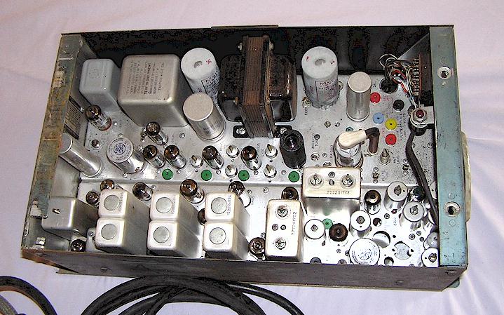
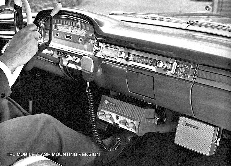
Back in those days, "solid state" amateur gear was just getting off the ground, especially if you bought used/ surplus gear. The two meter gear for some time was the much maligned 80 watt output GE "TPL" (Transistorized Progress Line) known mostly as the "toilet paper line" so it drew a fair amount of current. For a time I had the earlier GE "pre Prog" (known after the fact as "pre Progress line" because it was built before the "Progress Line" both of which were "all tubes, all the time."

One version of a trunk mount "Pre Prog." This is a low power VHF version, the one I had was UHF, and was larger, heavier, and used more juice. I don't remember, anymore, what it drew. By this time, the RR had a trunk mount battery

With the San Diego repeater (WB6WLV, still on the air today) back then, the "link" and control was on UHF, but both VHF and UHF was usually on the air "simulcast" (when they both worked). If you were careful with antenna placement/ design, and some tuned rejection cavities, you could run "full duplex" that is you could transmit and receive simultaneously

GEPP002.jpg


A front mount TPL. Mine was a "half and half" deal, about half was up front, the other was in the trunk, so it didn't take up QUITE as much room up front

TPL1.jpg


Hell, I haven't been on 2 meters or UHF around here for a couple of years. Can't stand the ridiculous "conversations."
 
As 67Dart273 said, the wiring might be easier if you get an electronic Vreg for the early round-back alternators. I got one at Autozone or RockAuto for ~$11. It had the same terminals as the old mechanical Vreg, but was a thin chrome box. You then wire the square-back alternator as a round-back, i.e. just ground one of the 2 field terminals (either one). I think the Vreg above can handle the field current of the square-back fine.
 
-
Back
Top