Alt wiring questions

-

kempkan

Well-Known Member
Joined
Jun 30, 2009
Messages
166
Reaction score
2
Location
Latrobe, Pa
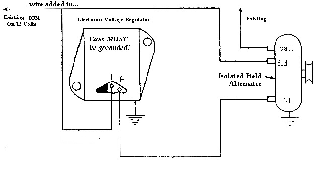
I recently put in a painless 8 circuit race system in my 73 dart with a 5 toggle (plus push button start) moroso switch panel. I have ignition, starter, fuel pump, fan, lights, and water pump all wired in with no problem. I just can't firure out were the alt and voltage regulator would hook up to. Im pretty sure there's a 18ga and a 14ga wire im not totally sure of the colors right now and I know the big wire is going straight to the battery and one goes straight to the voltage regulator but which one is it? Where does the other wire go? By the way I do not have the factory electronic ignition im running a msd digital 6al. The harness was hacked when I bought it. There's so many splices and butt connectors from the prev owner im not sure where it goes. Thanks for the input.
 
If possible do you know what part no. the Painless harness is?

What are you running for an alternator, that is, 70/ Later Mopar system, Delco/ Denso conversion, one wire, etc?

If you are running the stock Mopar setup, the regulator should look just like the drawing below.

The wiring going off the diagram at the top left labled "existing IGN on 12 volts" goes to your "switched IGN" in other words the same wire that supplies your IGN system.

The wire coming off the BATT terminal of the alternator represents the big output stud, and if you are not running an alternator, can go directly to a main battery buss, typically the big stud on the start relay.

chrysler_external_voltage_regulator_wiring.jpg


The other problem, of course, is that other than wiring errors, you may have a problem with either the alternator or regulator
 
The painless system I got was a prf-50001. As for the moroso switch panel its a mor-74131. The alt set up is the one like in the diagram above. I believe its the factory set up that belongs on a 73 dart v-8. Like I said there was so much spliced in everywhere I couldn't really tell what went where. Is the 18ga or the 14ga wire watching the ignition voltage in the diagram you gave me? I also need to know what wire and where it connects to the fld part of the alternator if it matters.
 
Not being familiar with the rest of your wiring, about all I can advise is "follow the diagram." The field connections don't matter, you can switch them around.

So the IGN wire from the regulator and EITHER field wire goes to switched IGN

The remaining field terminal is run direct to the regulator as shown in the diagram

The batt connection on the alternator, if you don't have an ammeter, runs direct to a good battery connection

Make sure the regulator is grounded "same as battery" and "same as engine block."

This appears to be the destructions for your wiring:

www.painlesswiring.com/Manuals/50001.pd

At the bottom of page 3 it shows pink no 18 wire, wire no 831 is "relay activation" for "ignition run."

This means that this wire should fire a RELAY which in turn operates ignition circuits. The output of that relay is what your ignition system, one of the field terminals, and the regulator IGN terminal should be hooked to.

BUT on page 5, it shows pink no14, wire no 820 "ignition coil." This appears to be direct wired, NOT using a relay. I'd guess there are some options with that harness.

One thing I detest about Painless and some others is that the do not bother to give you a wiring diagram.
 
I just got off of work so im going to try this tonight and see if all goes well. Thanks for the help. Wish me luck.
 
The harness was hacked when I bought it. There's so many splices and butt connectors from the prev owner im not sure where it goes.

I sure hope you removed all the hacks before you installed the harness. This could just be importing all sorts of problems.

As for the alternator hookup, X2 on what 67Dart273 says.
 
Yeah all the hacks got eliminated by the painless kit. As for the battery and alt wires they are all brand new the whole way back to the cutoff switch. I ended up splicing into the pink wire on the painless from the voltage regulator to watch ign volts. Worked perfect. I first fired it I had around 14.6v then slowly dropped to around 14.2v or so. I had the battery on and off while I was wiring the car to check for voltage so the 14.6 didn't surprise me. The battery may have been a little low. Thanks for the help we will see how she does on the track this summer. It will be the first time in this car. Thank you again.
 
The large red wire (at least 14 ga) goes from the alt through the wire harness and to the Red input side of the ammeter.

I would have to look up to be sure, but I think at least one of the green field wires goes to the ballast resistor or voltage reg.
 
-
Back
Top