Alternator

-

plydus340

Active Member
Joined
Jun 3, 2013
Messages
43
Reaction score
0
Location
marlow oklahoma
Is the wire on the alternator that goes to the green wire on the voltage regulator a ground? I should say this is on my 73 Duster. Thank you for any responses.
 
Not exactly. That green is the regulator CONTROL wire. It does functionally, so to say, "control the amount of ground" (resistance to ground) of the field circuit. It is NOT a ground wire.

If you unhook that wire, it should stop charging.

Now, please ask the "real question."

What is it doing that it should not be?
 
It's not charging. Can I just splice into it before it goes in the loom? After 8 years in a field the wire I was using is lost
 
Yup. You should be able to cut into the harness and find it. You should have the big black with eyelet, hooks to alternator output stud, and blue (switched 12v ignition) hooks to (either) field terminal, and the green hooks to the remaining. Electrically does not matter

Here's a simplified diagram. The green goes directly up to the indicated terminal on the regulator

Dual_Field_Alternator_Wiring.jpg
 
I have no voltage regulator on the Duster. I guess the one I had was a built in V.R.. The one I'm using needs one. I bought one today and will try to do it tomorrow. The alt I'm using hasn't got a plug on the field. Has a funny clip. Any ideas about this?
 

Attachments

  • IMG_20130618_182352_910.jpg
    48.3 KB · Views: 280
I cannot see what you are referring to. The picture you posted shows no regulator. NO Mopar aternator was ever "built in" although there are aftermarket (Powermaster) "hang on" regulators, that are a small rectangular box which bolts somewhere onto the alternator case, on OUTSIDE.

That last is not production, is not "normal," is a 3rd party deal

What/ where is the green wire and where does it go?

Someone may have incorrectly "converted" it to an earlier 69/ earlier regulator

Your 70/ later regulator should look like this, that is, the one that belongs on the car:

3438150NOS160-1.jpg[


A 69/ earlier can look like "several"

attachment.php


Some replacements are in a shorter case, and are solid state


Aftermarket replacement, can be used on 69/ earlier, or on 70/ later by grounding one field terminal

mtBmXZuQaLczaf-YvhTdKWg.jpg
 
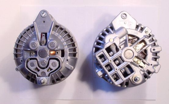
The alt has the funny clip. One field has the prong the other has the clip (instead of another prong). That is not the voltage reg I have. Has the triangle with two prongs.
 
Read through some of my threads. Do NOT allow some parts guy to talk you into accepting a "round back" alternator --which is what you have. You WANT a newer "square back"

De one on de right........................

squareroundcomp.jpg
 
Square back with the voltagr reg in the diagrahm. I have a square back I burned up years ago (cant remember how) in my shed I'll take for a core. Still kinda scared, but what's life without adventure.
 
Now you have me confused because the photo you posted above is not a square back...............
 
I'm confused by your confusion, 67Dart273. As I follow this, the round-back alternator in his photo is the one that he found is wrong (with your help) and he is going to return it and get the later squareback type. That is better because it puts out more current, and is correct for his car.

plydust340,
Since the factory field wire is apparently broken in the harness (verify w/ a multimeter), you might consider mounting the Vreg beside the alternator on the inner fender. That keeps the new wires short, and the setup simple and understandable. I did that in my 65 Dart, and also used a squareback w/ the later Vreg (triangle connector). Not sure why the factory didn't do that since the firewall is cluttered enough as is.
 
I have the square back alt, the correct voltage regulator, and a ballast resistor. The instructions say to hook the one field to a ballast resister that leads to the + side of the coil. I have a Mallory Hyfire VIA microprocessor controlled ignition system going to a Accel Super coil, then to a Mallory Unilite distributor. The signal varies on the coil where it is supposed to be hooked up. This is all controlled through a switch on my shifter base. Where should I run the field wire? I will use a ballast resistor.
 
The instructions say to hook the one field to a ballast resister that leads to the + side of the coil..


NO

The field and regulator "I" (ignition) terminal must hook BEFORE the ballast, on the IGNITION SWITCH side of the ballast. That is the way it's wired from the factory

Look at the simplified diagram I posted earlier. The dark blue "ignition run" (Mopar calls it IGN1) comes out of the bulkhead connector, terminates at one end of the ballast, and one way or the other, branches off and feeds "other components." This varies year to year but generally is

of course the ignition (ballast)
the regulator IGN (I) terminal
the blue alternator field

electric choke heater if used
idle solenoid if used
smog doo dads on some year models


Also, and there's many threads on this, it's very important to be sure this dark blue feed is not suffering voltage drop, because not only does it power the above "stuff," it's also the voltage source for "voltage sense" for the regulator. If that point out of the bulkhead is low, the regulator compensates by jacking up the alternator output until it comes "up."

If you can post the specific link to your ignition system destructions, that might help as well
 
I found a 11.5 that comes on with the key on the firewall near the bulkhead connector. It's on the four pronged connector ( ballast connector ?). Is that what we want?
 
If the correct terminal is what you have found, it is low and it will cause overcharging. I need a link for the destructions to whatever your ignition is, and how it's wired.


Forgettting the Hyfire for a moment, let's consider "factory." Whether you have a 2 or 4 prong resistor, the factory wiring is the same as the diagram I posted. That is 1/2 the 4 prong resistor is the same as the diagram above

That diagram does not show everything, but look at the top of the ballast resistor. If you have a 4 prong resistor, that will be the end of the ballast which is jumpered together.

Now, the PATH of that part of the circuit is as follows:

From battery -- to starter relay stud -- fuse link -- bulkhead connector -- ammeter circuit -- ignition switch connector -- through the switch -- back out the switch connector on dark blue "run" wire -- back out the bulkhead -- and to the ballast resistor.

Now ANY point in that path listed above, or MORE than one can be a cause for drop. It goes through the bulkhead connector TWICE -- once on the way IN from the battery, and once coming back OUT from the key, on the dark blue. IF THAT is the wire you have found, you need to fix the problem, or you will have overcharging issues.

Photos of what you are up to would help
 
Page 6, Figure 10. The battery may be a little low because of no charging. Thank you so much for helping...
[ame]http://prestoliteperformance.com/media/instructions/mallory/Mallory_Instructions_hyfire_%206A_6AL_wiring_diagram_6852M_6853M_0001.pdf[/ame]
 
The wiring was eat up from rats after sitting in a field for 8 years. When I bought the car it had been a hot rod many times. It had been spliced, panted over, and southern engineered many times. Then rats lived in it for 8 years. The guy who put it back together is a chevy guy, and he wired it like a race car with power switches through a distrbution block ect. The lights work, and blinkers to make it legal, no wipers, no horn. Pics if you want em, but I think you have an idea of what we got now.
 

Attachments

  • Taz motor.jpg
    65.9 KB · Views: 237
Part of the trouble may be from overcomplication, LOL. I don't believe there's any reason to keep the mopar ECU or ballast with your ignition setup. Somebody can correct me, but I think your ignition box is same as MSD?
 
OK, look, we are back to the very basics. For a minute, forget everything except the very basics. You have the ignition switch "in there" and you have the bulkhead connector.

The ignition switch supplies power in run, accessory, start, etc

There are only THREE switched lines coming from the switch through the bulkhead

1--start, yellow or yellow tracer on most cars, comes right from the ign switch, through the bulkhead, and to one of the push-on terminals of the start relay. Hot in start only

2--Coil resistor bypass, traditionally brown, comes direct from the ign switch, through the bulkhead, and hooks to the coil + side of the ballast resistor. Hot only in start, not "run."

3--MOST IMPORTANT "run", traditionally dark blue, comes from the ign switch, through the bulkhead and is the wire we have been talking about. Hot ONLY in run, NOT start.

THIS IS THE ONLY switched "hot wire" that is "hot" in run.
 
I have the power supply to the ign wired to the switch on the shifter. It is hot only when the car is running. That would be very easy to splice into. Short wires to the alt. would look a lot cleaner.
 
-
Back
Top