difference in 1.5 vs 1.6 magnum rocker

-

71dustar

Well-Known Member
Joined
Nov 14, 2007
Messages
1,022
Reaction score
8
Location
Fountain Hills, Az
ill be using the eddy alum mag heads and wondering whats the best ratio rocker arms for my 408 engine. what brands do you guys prefer?
 
I wasn't aware that 1.5's were available for the magnum head as 1.6's were stock. Stick with the 1.6's.
 
I was told by my engine builder that the difference is that the 1.6 will give you a higher valve lift, same as a bigger cam would (my 360 is not magnum and has 1.6 instead of 1.5 and a stock cam)
 
they have 1.6 or the 1.7's from MP. The thing about larger ratio is, however, you could easily hurt your valvetrain geometry with a larger-than-stock ratio, especially if all the rest of the valvetrain components are stock. Here's why:

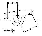
A rocker arm is simply a mechanically advantaged lever that translates camshaft data into valve actuation. The mechanical advantage is defined by a rocker's ratio. The standard small-block Chevy (SBC) uses a 1.5:1-ratio rocker arm. In other words, the rocker-arm tip (output) moves 1.5 times the displacement of its pushrod socket (input), or camshaft-lobe lift. The 1.5:1-ratio rocker arm translates 0.350 inches of camshaft-lobe lift into 0.525 inch of valve lift (0.350 inch x 1.5 = 0.525 inch). By increasing the rocker-arm ratio, it's possible to increase valve lift without ever touching the camshaft. A 1.6:1-ratio rocker arm translates the same 0.350 inch of camshaft-lobe lift into 0.560 inch of valve lift (0.350 inch x 1.6 = 0.560 inch). This is a lift increase of about 6.7 percent. Valve lift can typically be increased as much as 10 percent by increasing rocker ratio.

But because a rocker arm's fulcrum rotates in a radius, this could move your contact point on the valve stem outward, causing a bad contact pattern.

rockerarm2.jpg
 
eddy magnum aluminum heads use small block chevy 3/8 stud rockers...

i would use the 1.6....that is what i bought for my magnum heads....
 
I experimented with both 1.5 and 1.6 arms on a magnum head and the 1.6 does have better geometry. Didn't have a 1.7 to try. It might even have better geometry yet. All depends on how it's designed. The reason the 1.6 had better geometry than a 1.5 rocker was the point where the pushrod engages into the rocker arm is moved closer to the rocker arm fulcrum. That helps to straighten out the bad pushrod to lifter angle small blocks have. If the 1.7 has the pushrod point moved in farther yet it will help even more.

1.6 rockers will also create a slightly faster rate of lift.
 
they have 1.6 or the 1.7's from MP. The thing about larger ratio is, however, you could easily hurt your valvetrain geometry with a larger-than-stock ratio, especially if all the rest of the valvetrain components are stock. Here's why:


But because a rocker arm's fulcrum rotates in a radius, this could move your contact point on the valve stem outward, causing a bad contact pattern.

rockerarm2.jpg

I was under the impression that mfr's increased the ratio by bringing the pushrod cup IN rather than moving the valve contact tip OUT. In your diagram, shortening X rather than lengthening Y. Am I wrong, or do some do it one way and some do it the other way?
 
1.6 will open the valve faster and further and if .002 is added to the original lash setting for every .1 more in ratio, the valve timing shouldn't be affected.
 
SC - yes, this is how they do it, and why many people have issues when using 1.6 or 1.7s with some heads without elongating the pushrod holes.
If you can, the higher ratio will give a faster rate of lift and closure and especially on the exh side this has proven to produce some power. I would go with 1.6s (keep in mind almost ALL cams are sepc'd for 1.5s so make sure to convert for the lift and account for the extra pressure needed.
 
Like I said 71dustar, stick with the 1.6 ratio that was factory for your heads.

Leblanc, you have a great point in regards to ratio in LA heads.

Sharpie, your diagram is fundamentaly flawed in regards to the trig involved in Magnum and or LA head/valve geometry and is incredibly over simplified. No disrespect intended, I can't wait to explain!

70AAR is correct.

Fishy is right in regards to 1.6 rockers and Mag heads. I haven't drawn out 1.7's yet.

SC is also correct.

I don't understand wilds post.

Moper is also correct.

I plan on making a a very comprehensive post on Mopar valve geometry very soon, but right now I'm studying multiprotocol label switching so I can be a rock star at my job interview on Thursday. :) MPLS seems to throw the standard OSI model into a tizzy, lol.

Back in a few days on this whole deal. Like I said before, just run the 1.6's on a Magnum head, that's what it was designed for. :)
 
Sometimes the roller end does get pushed out, Harland Sharps are a good example. The huge trunion area doesn't allow the pushrod point to move close enough to the shaft centerline, so, you have to move the roller away from the shaft centerline. That causes another set of issues, DAMHIK!

AndyF had a pic of a group of rockers for BB, all on a shaft, and the difference in roller location was interesting!

I'm guessing the diagram is simplified because of the compund angle. Same reason SB mopars don't get anywhere near the stated advertised lift
 
But because a rocker arm's fulcrum rotates in a radius, this could move your contact point on the valve stem outward, causing a bad contact pattern.

Sharpie, The text is correct. I can't see the diagram on my pC at work.. but I can tell you I think youare a little off with this statement. The fulcrum is a single point around which the lever (the rocker) rotates. The radius of the rocker is a straight line drawn accorss the distance from the rocker to valve contact point (roller tip) to the center of the fulcrum point. The pushrod side has it's own radius that is different from the valve side. If the geometry is correct, regardless of the type of rocker (shaft, stud, pedestal) the rocker tip sweeps accross the valve stem tip because the path the tip follows is an arc. What you aim for is at mid lift of the cycle, the radius of the rocker arm is perpenicular to the centerline of the valve stem. Because of the arc's resulting sweep, this means the contact point is at it's furthest point from the fulcrum point, or just off-center of the valve tip towards the exh side (outside) of the head. However, at full lift, the contact point should be centered on the valve tip. This same principal applies to the pushrod side, except the issue is the distance between the pushrod's upper mid-section and the rocker shaft side of the pushrod hole in the head. As the rocker is pushed up, the cup effectively moves in towards the rocker and the pushrod rubs. The higher the rocker ratio and higher the lift, the more likely the problem will occur.
 
Sharpie, The text is correct. I can't see the diagram on my pC at work.. but I can tell you I think youare a little off with this statement. The fulcrum is a single point around which the lever (the rocker) rotates. The radius of the rocker is a straight line drawn accorss the distance from the rocker to valve contact point (roller tip) to the center of the fulcrum point. The pushrod side has it's own radius that is different from the valve side. If the geometry is correct, regardless of the type of rocker (shaft, stud, pedestal) the rocker tip sweeps accross the valve stem tip because the path the tip follows is an arc. What you aim for is at mid lift of the cycle, the radius of the rocker arm is perpenicular to the centerline of the valve stem. Because of the arc's resulting sweep, this means the contact point is at it's furthest point from the fulcrum point, or just off-center of the valve tip towards the exh side (outside) of the head. However, at full lift, the contact point should be centered on the valve tip. This same principal applies to the pushrod side, except the issue is the distance between the pushrod's upper mid-section and the rocker shaft side of the pushrod hole in the head. As the rocker is pushed up, the cup effectively moves in towards the rocker and the pushrod rubs. The higher the rocker ratio and higher the lift, the more likely the problem will occur.

Sharpie,

The inset text is correct that you posted but the diagram was wrong. Close though! :)

Moper is again correct in stating that the ratio would be calculated with a straight line from the topmost portion of the pushrod pocket to the axis of the roller bisected by the axis of the rocker shaft.

As the axis of the rocker shaft (or bearing in magnum rollers) is moved up or down, the contact patch is affected. This is easy to set up on magnum (chevy style) rockers by varying the pushrod length as this will move the axis up or down at a given preload. An LA head is a different story altogether. The axis of the rocker shaft in relation to the valve stem tip can only be moved by shimming the rocker shaft up or varying the installed height of teh valve. A crappy valve job with the installed valve stem tip too high, low or a combination of both can wreck the geometry as the rocker shaft axis cannot be changed on per valve basis like with magnum or chevy rockers. This is why it pays to have someone who knows what they doing cut your seats and valves.

Another issue is the distance between the axis of the rocker shaft on a LA engine and that flat line between the pushrod pocket and roller that we discussed earlier. Increasing or decreasing this distance will also effect the roller tip contact patch, and this can cause unforseen nightmares with aftermarket parts. I've always had good luck with Crane rollers as they always seem to be right on the money, but I bring my rockers and shafts in when I have my heads done now, as I no longer work in a shop where I can do it myself.

Most quality rocker manufacturers will tell you how many threads should be showing below the rocker at your given preload for correct pushrod cup oiling. Once the contact pattern is set up at your favorite head shop, you can make, borrow or buy an adjustable pushrod to set that distance. Once again, on a LA shaft mounted rocker motor, pushrod length does not set rocker arm/valve stem tip geometry.

Like Moper said, higher ratio rockers will change the pushrod geometry but not the valve tip contact area and some judicious grinding may be necessary. This is why mocking up a build is so important before squashing those expensive head gaskets.

All in all, this makes setting up an LA head kind of a *****, but when done right, it's darn near bullet proof.

In regards to ratios over 1.5 being detrimental, they are only if used or applied incorrectly. For instance, Ford 351C and 400M engines use a 1.73 ratio rocker from the factory. I would imagine that a 1.7+ ratio rocker on a LA would be pushing it and a builder would be better off getting a bigger cam as the pushrod geometry may require some serious head mods as well as increase the stress on the pushrod, which would require stronger heavier pushrods which will add weight to the valvetrain. That's not good. However, if someone is running an engine with heads that show increased flow with the added lift of the increased rocker ratio and they are running a small cam for driveability reasons, there can most certainly be a power advantage throughout the entire rev range.

Sorry so wordy on this. One day soon I'll make a post about this with pics and diagrams. :)
 
-
Back
Top