Ecu 5pin's on system ballast 2 slots

-

Tof

Well-Known Member
Joined
Aug 20, 2005
Messages
49
Reaction score
0
Location
Auchel (FRANCE)
Hi all ,

well actualy on my small block i have a ballast/coil resistor(?) 2 slot with distributor at contact set .

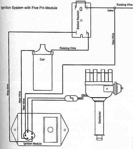
I have a distributor magnetic and one Ecu 5pin with coil 12v , the typical wiring is this ..

Ignition_System_5pin-2b666c8de81a302229b1a5bdb15c8fe4.jpg


But here i see this ....

MoparPerformanceelectronicignitionw.png


My question , can i use my system ecu 5 pin with a ballast 2 slot ?

Cordialy
 
The REAL question is, DO YOU REALLY HAVE a 5 pin ECU

Some 4 pin ECU's ONLY HAVE 4 pins

Some 4 pin ECU's HAVE ALL 5 pins. So get your ohmeter and probe the "5th" pin and see if there's any continuity anywhere.


Next to answer your question:

If you REALLY have a 5 in ECU, you MUST use a 4 pin resistor
 
What , there is some ECu with 5 pin's in appearance but internal its a 4 pin's ?
 
I think he means a 4 pin ballist.\\:D/


Nope. Meant just what i said

A 5 pin ECU MUST have a 4 pin ballast

A 4 pin ECU can use EITHER 2 or 4 pin ballast

A 4 pin ECU CAN have either 4 or 5 pins. The 5th pin will be unconnected internally
 
67DART273 is right on the money. I had this problem recently diagnosing a no start Road Runner in Kingsland for a friend. He had had several "experts" try and come over and get the car running. All of them failed to use one wiring diagram that I DID use. It was the factory stock diagram for the 74 Road Runner, which DOES use a 5 pin ECU. Once I rewired the ignition for the 5 pin unit, it fired right up after five years. You need to remember,that diagram up there you posted with the orange box is the aftermarket system from Mopar Performance. If your system is a five pin system that USES the fifth pin, it will not run wired by that diagram.
 
Well this some news ,

I check my ecu for the connection of the fifth pin and on some manual this fifth is at right and on other it's at left for me no problem i check two and this the result with a "diode ohmeter" ...

p2402111657.jpg


And

p2402111658.jpg


Now for you its a real 5 pin's or a 4 pin's with the fifth pin not connected in internal ?
 
This diagram is correct:

3129021-5pin.jpg


NOTICE how the resistor is wired, and is identified by an "open hole" on one end. The resistor MUST be wired this way

The pin you want to check is your bottom picture. I'd hook up the leads to the meter, see what you read, then TURN THEM AROUND (reverse polarity) and see what you read that way.

Post back the readings if you are unsure.
 
Well effectively wen i reverse the polarity at this fifth pin i have a other result ...

p2402111955.jpg


I do certainly use your diagram with ballast 4 slot with this ecu ....
 
I'd say you have a legitimate "5 pin" there. The reason the readings are different--and of course why I suggested it, is that you are reading through various solid state components---transistors, resistors, diodes, etc, and when you reverse the meter polarity, the various transistor and diode junctions change the reading.

If it had read "infinity" or dead *** ground (close to zero) both ways, I'd have said you have a 4 pin.
 
Ok fine , i do a order at Rockauto for a ballast 4 slot and some parts .

Thanks for all , you are the best my bug is closed !
 
YEAHHHHHHHHHHHHHHHHHHHHHH !

Thanks for all man's , my converting of my distributor mechanical with ballast 2 slot to distributor with Ecu and ballast 4 slot is operational .

At the second start >>>> Vraoumm !

You are the best .................. hmmm i repeat all time this here ???
 
We now require pictures or video of tire smoke to ceritfy that car is running properly !!
 
-
Back
Top