You are using an out of date browser. It may not display this or other websites correctly.
You should upgrade or use an alternative browser.
You should upgrade or use an alternative browser.
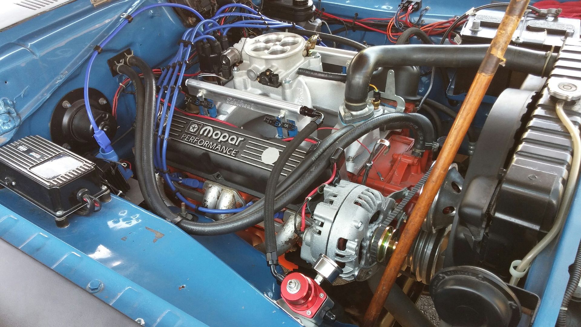
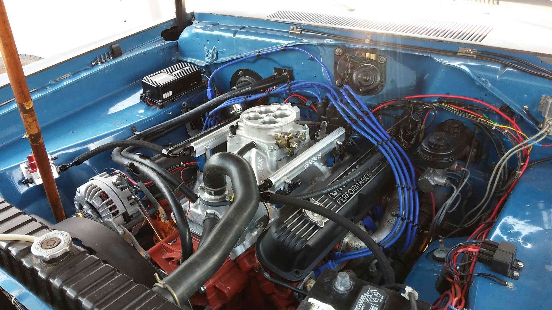
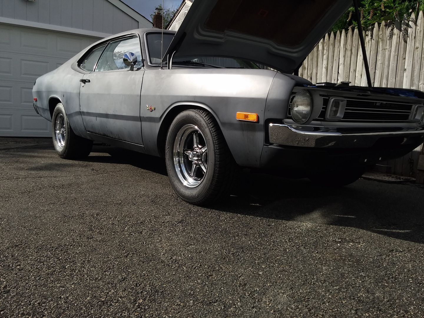
EFI install on my 360
- Thread starter 1972_Demon
- Start date
-
buckshotbishop
Old Soul
I hope you post up some good photos and details. What are you using for ignition / trigger?
2nd
1972_Demon
Demonic Member
I'm using a lean burn distributor. Needed something with no mechanical or vacuum advance, so it was the easiest choice.
I'm using a lean burn distributor. Needed something with no mechanical or vacuum advance, so it was the easiest choice.
So it's batch fired?
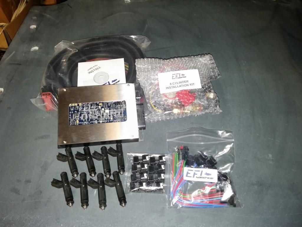
Those appear to be the Mustang 5.0 style Bosch style injectors, no?
txstang84
Well-Known Member
Those appear to be the Mustang 5.0 style Bosch style injectors, no?
I think they're actually the Siemens pencil style...I haven't seen the Bosch styles on factory Mustangs the late 90s or so.
1972_Demon
Demonic Member
txstang84
Well-Known Member
Ah, cool deal. Watching
1972_Demon
Demonic Member
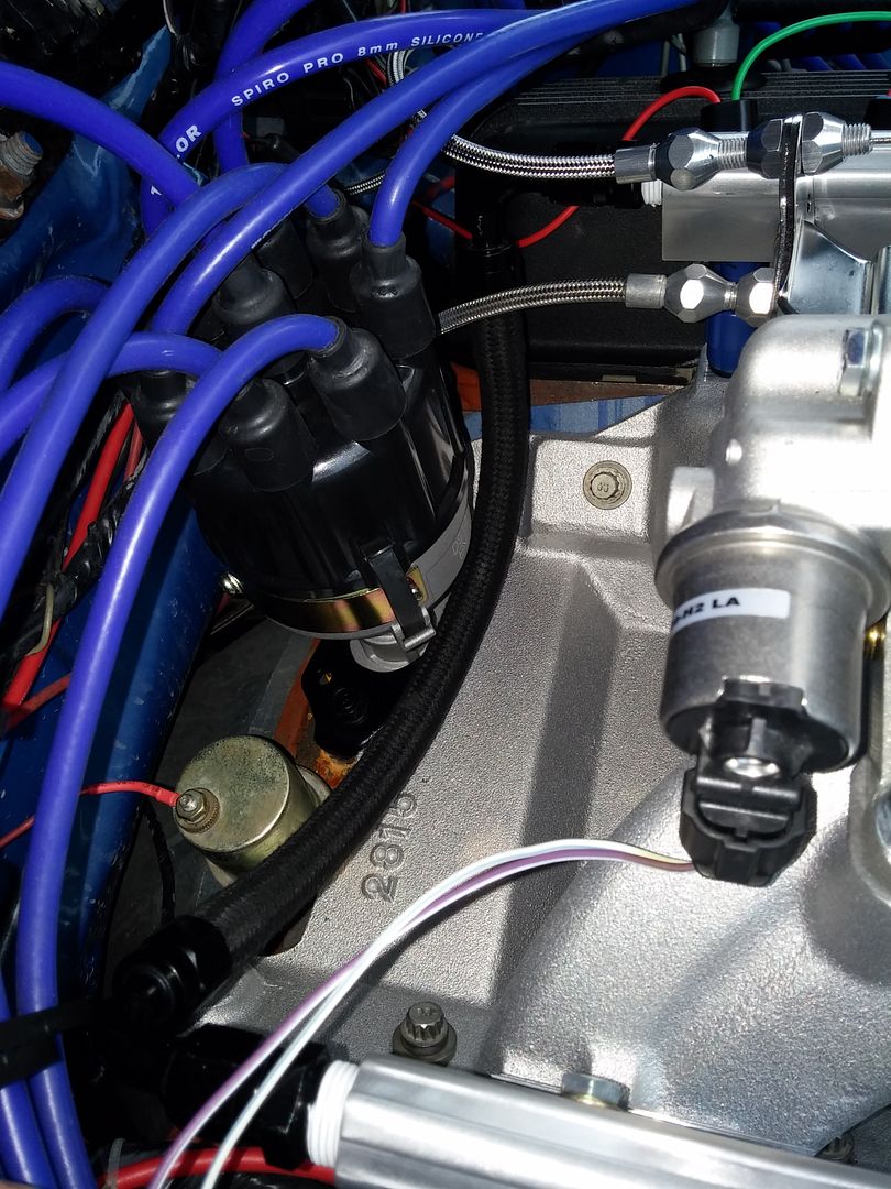
More progress.......
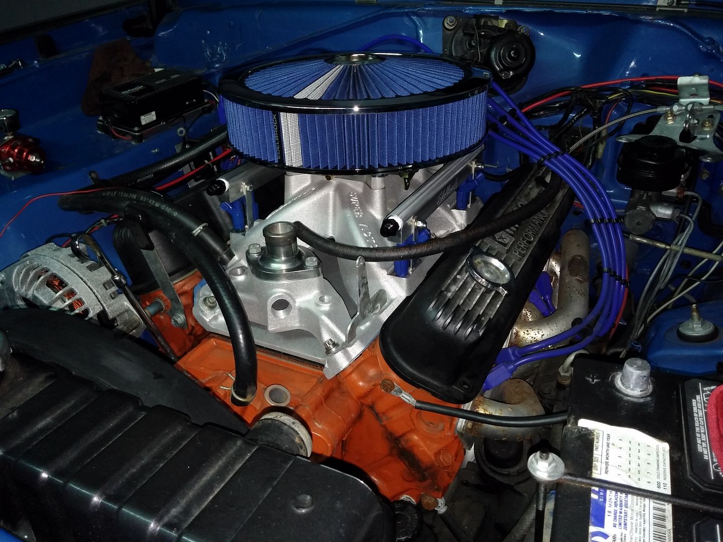
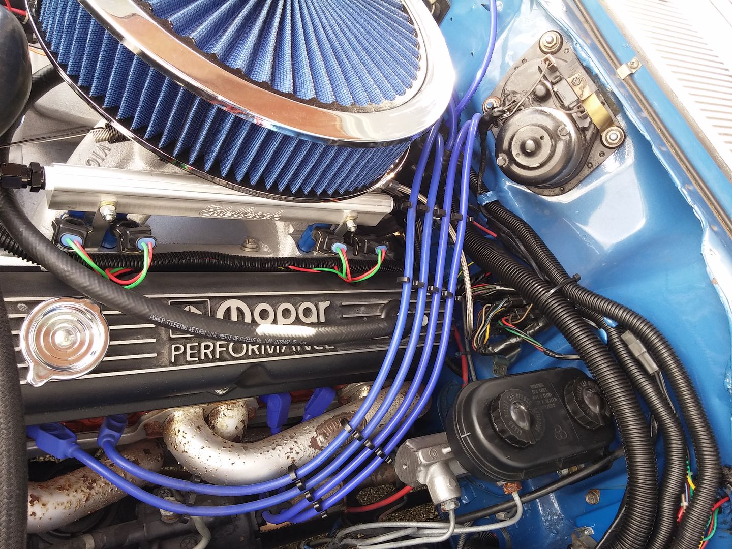
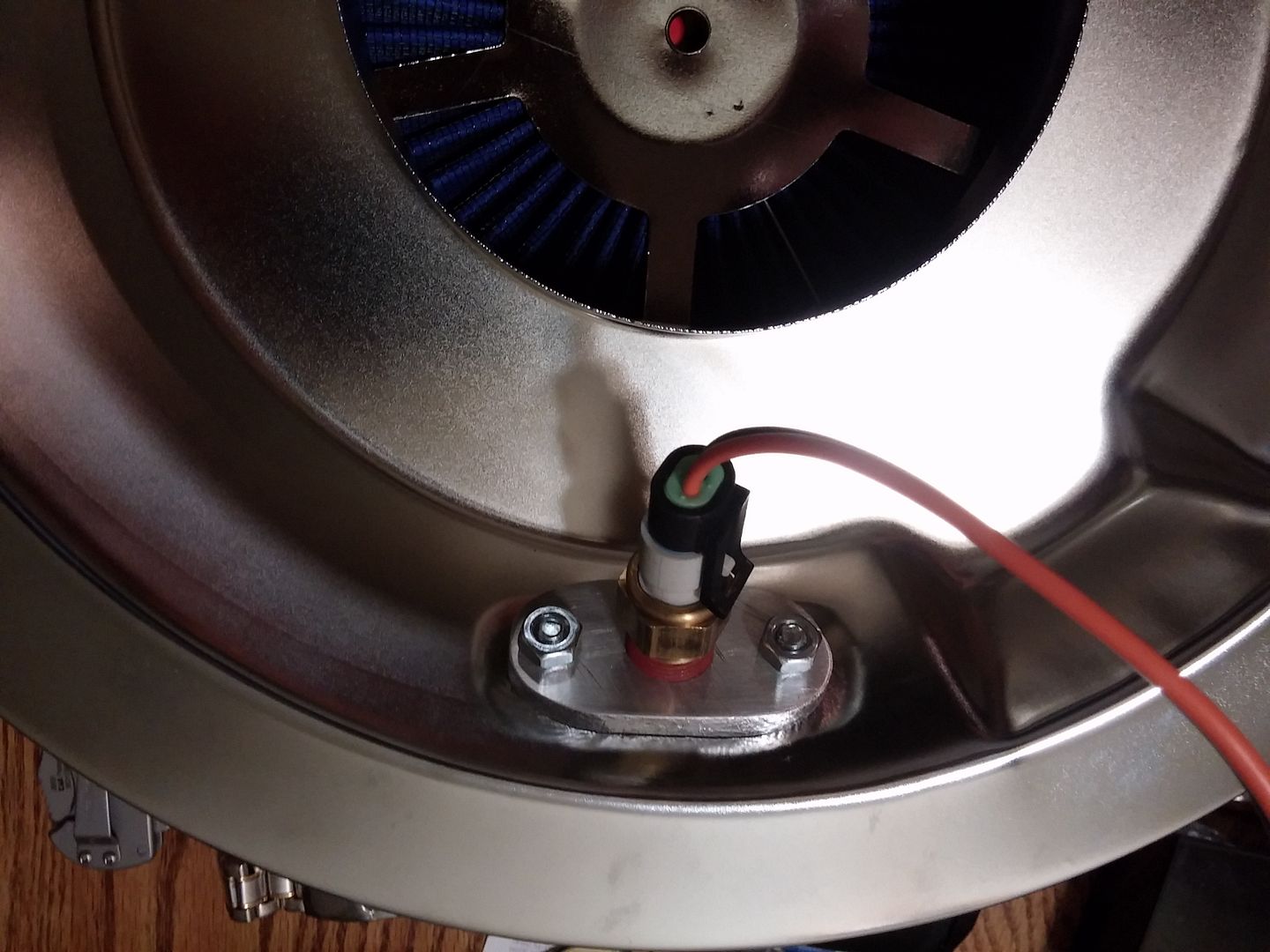
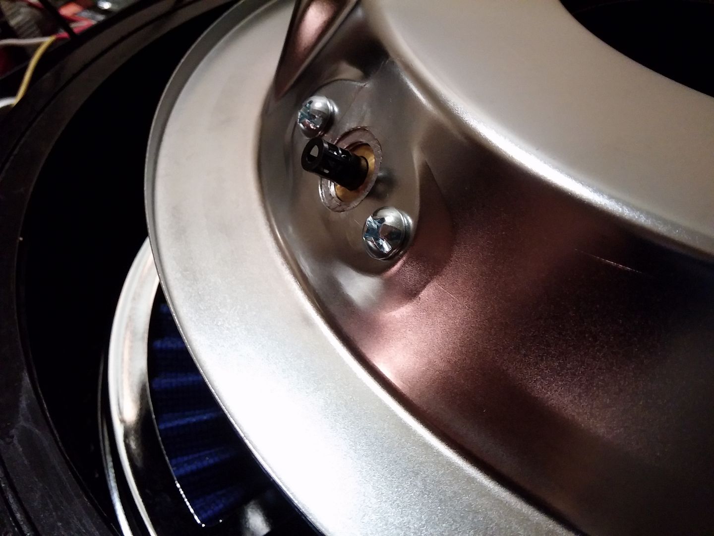
Air intake temp sensor mounted in air cleaner.
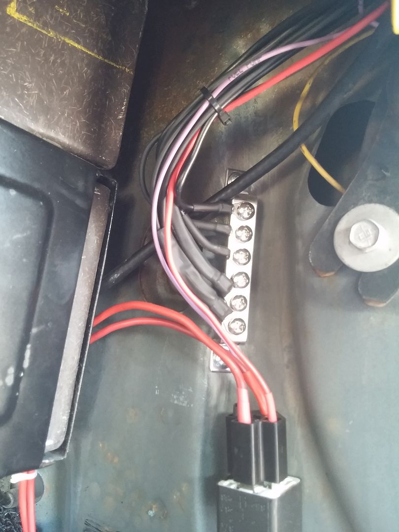
Pigtails everywhere........
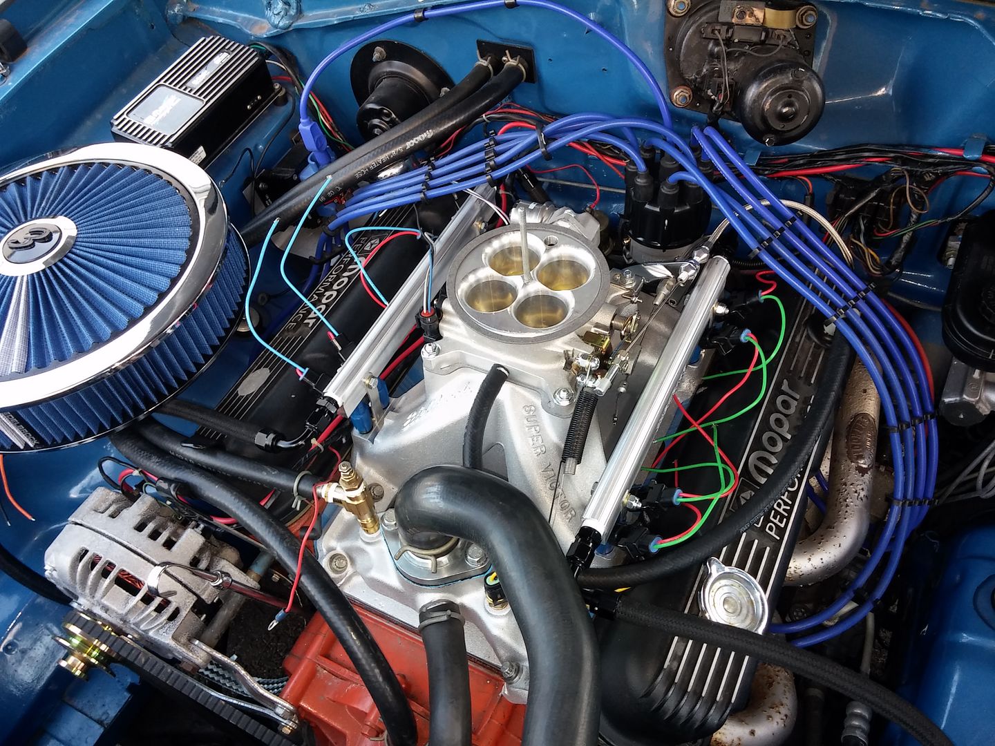
Rear connection on fuel rails.
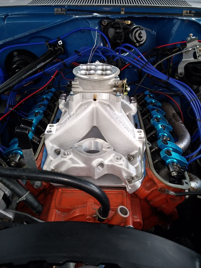
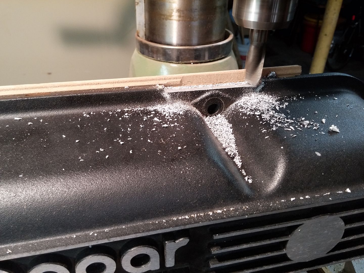
A little bit of massaging to the valve covers to clear the Super Victor intake.
I should be able to get the rest of the wiring completed tomorrow. Maybe even try to start it for the first time with the EFI.
Air intake temp sensor mounted in air cleaner.


Pigtails everywhere........

Rear connection on fuel rails.

A little bit of massaging to the valve covers to clear the Super Victor intake.

I should be able to get the rest of the wiring completed tomorrow. Maybe even try to start it for the first time with the EFI.
Mad Dart
Nothing to see Here!
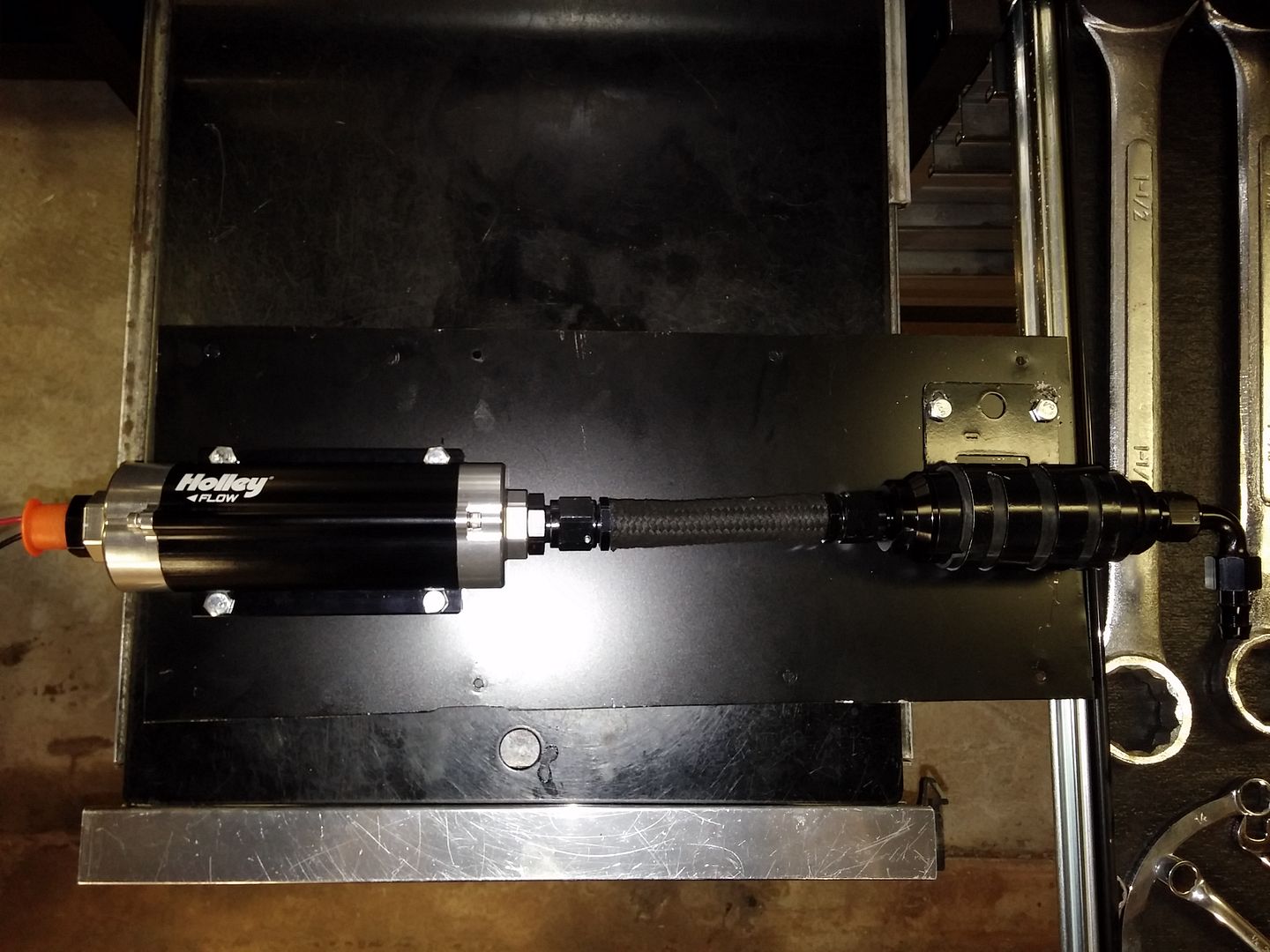
Can you explain how you are routing your fuel lines. From tank to pump to what first?
Where is your return plumbed into the system? If you have the fuel pump hitting the regulator first you are asking for problems. Guys have burnt up pistons like that with EFI. You may have it like that. I can't tell in the pictures.
The Fuel Rails should be tied together as a U with fuel coming in the beginning of the U from the Pump and the return on the end of that U so the Fuel Pressure is full tilt boogie at the injectors and bleeding off after hitting all of them.
Intake air temps in the Air filter...... Shouldn't it be after the butterfly's down on the intake or on an aluminum spacer under the throttle body? I think you are going to get false readings like that.
1972_Demon
Demonic Member
My feed line comes up the drivers side of the car. Into the fuel rail on that side then loops to the other rail in the back. Then out the front to the pressure regulator. Old fuel line is now the return line.
As far as the temp sensor, most newer EFI cars have the temp sensors mounted in the air filter tube before the throttle body.
As far as the temp sensor, most newer EFI cars have the temp sensors mounted in the air filter tube before the throttle body.
Mad Dart
Nothing to see Here!
My feed line comes up the drivers side of the car. Into the fuel rail on that side then loops to the other rail in the back. Then out the front to the pressure regulator. Old fuel line is now the return line.
As far as the temp sensor, most newer EFI cars have the temp sensors mounted in the air filter tube before the throttle body.
Good on the fuel line routing! You have done your homework.
Yeah the newer cars have knock sensors as well & they are mostly all aluminum. Just be careful
of the readings. The temps under the butterfly's on the intake will be a lot warmer than in the air cleaner. You don't want it detonating, it could be an early end to an engine like that. Just something to be mindful of.
You are doing some nice work.
I too am installing an EFI on my car as I type this and it will be Procharged as well.
You can see my progress here soon on my Scamp Attack thread in my signature.
1972_Demon
Demonic Member
I got it started this afternoon. I'll spend the next couple days trying to tune it.
At least I can clean up the wiring now that it runs and put the interior back together.
I'm hoping to get it to the track this weekend. Not sure if that's going to happen yet.
[ame="http://vid197.photobucket.com/albums/aa127/98_snake_bite/efi_start_zpshiddnm9j.mp4"]http://vid197.photobucket.com/albums/aa127/98_snake_bite/efi_start_zpshiddnm9j.mp4[/ame]
Mad Dart
Nothing to see Here!
Sounds good!
goldduster318
Overzealous Car Modifier
Nice!
I will be installing a lot of similar parts on my 340. I went with the Holley throttle body (has more sensors in it) and a Megasquirt 3 pro. I have an Aeromotive Phantom for the fuel tank.
Going SFI and coil-near-plug as well. Stay tuned for that!
I will be installing a lot of similar parts on my 340. I went with the Holley throttle body (has more sensors in it) and a Megasquirt 3 pro. I have an Aeromotive Phantom for the fuel tank.
Going SFI and coil-near-plug as well. Stay tuned for that!
1972_Demon
Demonic Member
Criscobath
Well-Known Member
Very cool.
Just wondering why you didn't go w/ one of the new plug-n-play throttle body fuel injection setups?
It seems like a much easier route to the same end.
Just wondering why you didn't go w/ one of the new plug-n-play throttle body fuel injection setups?
It seems like a much easier route to the same end.
txstang84
Well-Known Member
Awesome
ugh. quicktime.
1972_Demon
Demonic Member
Very cool.
Just wondering why you didn't go w/ one of the new plug-n-play throttle body fuel injection setups?
It seems like a much easier route to the same end.
I wanted to control timing also.
That's what is giving me tuning headaches right now. Getting strange RPM spikes. I may just put my old distributor back in for now until I get it figured out.
mguner
How many is too many?
I wanted to control timing also.
That's what is giving me tuning headaches right now. Getting strange RPM spikes. I may just put my old distributor back in for now until I get it figured out.
Someone mentioned that these mopar distributors can give different signals depending on polarity of the wiring.....
1972_Demon
Demonic Member
Yes, I saw something about trying to swap the wires around. I just haven't got around to trying it yet.
I may just go with the MSD crank trigger setup if I can't get it working.
I may just go with the MSD crank trigger setup if I can't get it working.
KitCarlson
Well-Known Member
Instead of swaping polarity, static check the reluctor/pickup location for your base timing. Example, if your light shows 12 degrees BTDC at idle, set the crank there, pop the distributor cap. If the trailing edge of a reluctor tooth is at the pickup, all is well. If the pickup is near the middle between teeth, then swap and reset timing. Also check plug wires indexed correctly. If the polarity is incorrect, the rotor phase will point between the towers, and timing may vary, because in between teeth is not an edge. It is also possible for spark to flash the pickup, creating additional triggers ... not good for electronics.
If your polarity is correct:
Depending on your wire routing, there might be a noise issue. Noise introduced on the pickup leads will generate false triggers. An example is pickup wires interlaced with plug or coil wire. In any case false triggers result in RPM peaks. Pickup leads should be twisted pair or shielded, check that distributor is grounded. The o-ring, painted clamp, and anodize on aluminum distributor can in rare cases leave distributor ungrounded. A distributor ground wire is a good addition.
I have never used MS, nor had a similar problem myself. I do know the electronics involved, so making my comments based on that, and your description of problem.
Mad Dart
Nothing to see Here!
Yes, I saw something about trying to swap the wires around. I just haven't got around to trying it yet.
I may just go with the MSD crank trigger setup if I can't get it working.
Don't waste your time on an MSD flying magnet crank trigger. They work like crap on EFI. They only send data every 90* of crank rotation. Been there and done that..... Dual sync distributors are junk as well, I tried that too. Not enough info is sent to the ECU
Get a 36-1 wheel for the crank trigger. This way your ECU will get data every 10* of crank rotation.
Modify your lean burn dizzy for a new sensor to pick up the cam signal only. I modified a lean burn dizzy with the sensor that is out of stock & also modified a nascar reluctor in the same lean burn Dizzy to grab the cam signal. The reluctor in the lean burn dizzy is pot metal and the prongs are very small. Throw some new technology in there, it is cheap.
I used the same Sensor on the crank and made my own brackets that were adjustable.
With this set up you will be way better off for sure.
Most everything you need is on this page....
http://www.diyautotune.com/catalog/trigger-wheels-c-48.html
[ame]http://youtu.be/dD4vuNSO8cg[/ame]
-
Similar threads
- Replies
- 0
- Views
- 243
- Replies
- 0
- Views
- 345
- Locked
- Replies
- 2
- Views
- 364
- Replies
- 0
- Views
- 882
- Replies
- 0
- Views
- 583

