Working on cleaning up the wiring in the engine bay. I wanted to run the alternator wiring direct to starter relay with a circuit breaker with reset, bypass the amp meter, clean up connections there and run wiring to some sort of fusable distributon block. i also have a small underdash amp that needed direct power. I also purchased the headlight wiring and relay kit from rob (crackedback) to help out the headlights. After discussions with Rob, I decided I would draw up some kind of diagram for other member to see and chime in. Any comments are welcomed but please not ...I am not a electrical expert and used a program to the best of my abilities to try and draw this up for you guys to see.
You are using an out of date browser. It may not display this or other websites correctly.
You should upgrade or use an alternative browser.
You should upgrade or use an alternative browser.
New Alternator/amp bypass set-up
- Thread starter SB69GTS
- Start date
-
BillGrissom
Well-Known Member
Basically sound. You mean "starter relay" (per drawing). The "solenoid" is part of the starter (thing that goes "clunk"). Your wire sizes seem a bit thick to me. 4 awg to the fuse box seems over-kill, especially since your new amp is direct-wired. The factory used 12 awg. I expect your amp turns off so it doesn't drain your battery while sitting. For a 70 A square-back alternator, 6 awg cable is probably fine. I recall that is what Magnum engines used (re-purposed that harness for my Dart). Some here have run 0 awg welding cable from their alternator, but seems silly and far beyond what Ohm might suggest. Copper is heavy and isn't cheap.
bbeep71
Well-Known Member
According to schematic you have Fuse Box, Light Swt. and Ign Swt. tied together by gray wires near amp bypass to 2- 25amp fuses at distribution box. Is that what you meant to do? I would think they would be separate to distribution box.
67Dart273
Well-Known Member
A pair of parallel no10 would be plenty big to feed the new fuse panel. I agree with Bill, no no4 is needed
You specify no6 from the alternator, no6 from the breaker to starter relay is large enough, and probably overkill.
You specify no6 from the alternator, no6 from the breaker to starter relay is large enough, and probably overkill.
slmiller243
Active Member
- Joined
- Mar 29, 2009
- Messages
- 42
- Reaction score
- 0
Like your solution. I don't understand why MAD has a double wire going back to the starer relay from under the dash. What did you use for the manual circuit breaker reset?
I think a lot of this is using what he has on hand and what others can supply.
The fuse block has a 4G wire running from it.
The two wires that come from the fuse block are spliced to the original red and black charging circuit wires that were in the bulkhead.
The fuse block has a 4G wire running from it.
The two wires that come from the fuse block are spliced to the original red and black charging circuit wires that were in the bulkhead.
67Dart273
Well-Known Member
Like your solution. I don't understand why MAD has a double wire going back to the starer relay from under the dash. What did you use for the manual circuit breaker reset?
I believe what you are seeing is the old original red and black ammeter wires which are not in PARALLEL
A pair of parallel no10 would be plenty big to feed the new fuse panel. I agree with Bill, no no4 is needed
You specify no6 from the alternator, no6 from the breaker to starter relay is large enough, and probably overkill.
I noted that its no.10 to feed the new fuse box, instead of looping underdash, I am running 2 no 10 wires to 2 25 amp fuses and a 12 gauge and 15 amp
The reason for no.4 is because I have a dist.block for a no.4 and its hard to find one with a smaller gauge in. These are the ones I use for stereo and amp hook-ups and they usually are 4 gauge or larger. I Checked all over and could not find a 6 gauge in and 10 gauge and smaller out.
Appreciate the comments and if you know of any fusible distribution blocks that take smaller in and out ... please drop me a line ...would rather use 6 but using what I have left over from other stereo installs
I used the no.6 welding cable because the alternator is rated a 95 amp and the wire is rated at approx 115 amps if I read it right ....gives me about 20 amps diff. and have a 110 amp breaker. I think this should be about right ....
I think a lot of this is using what he has on hand and what others can supply.
The fuse block has a 4G wire running from it.
The two wires that come from the fuse block are spliced to the original red and black charging circuit wires that were in the bulkhead.
Yeah ...thats how I meant to say it ....lol
Like your solution. I don't understand why MAD has a double wire going back to the starer relay from under the dash. What did you use for the manual circuit breaker reset?
The manual circuit breaker is a Cooper Bussmann CB185-110, its available in different amperage. Here's a link
http://www.cooperindustries.com/con...ve_marinecircuitbreakers/High_Amp_Marine.html
Was think of this one for the distribution block but using what I have here
http://www.cooperindustries.com/con..._distribution/fuse_panels/pdm-ami-series.html
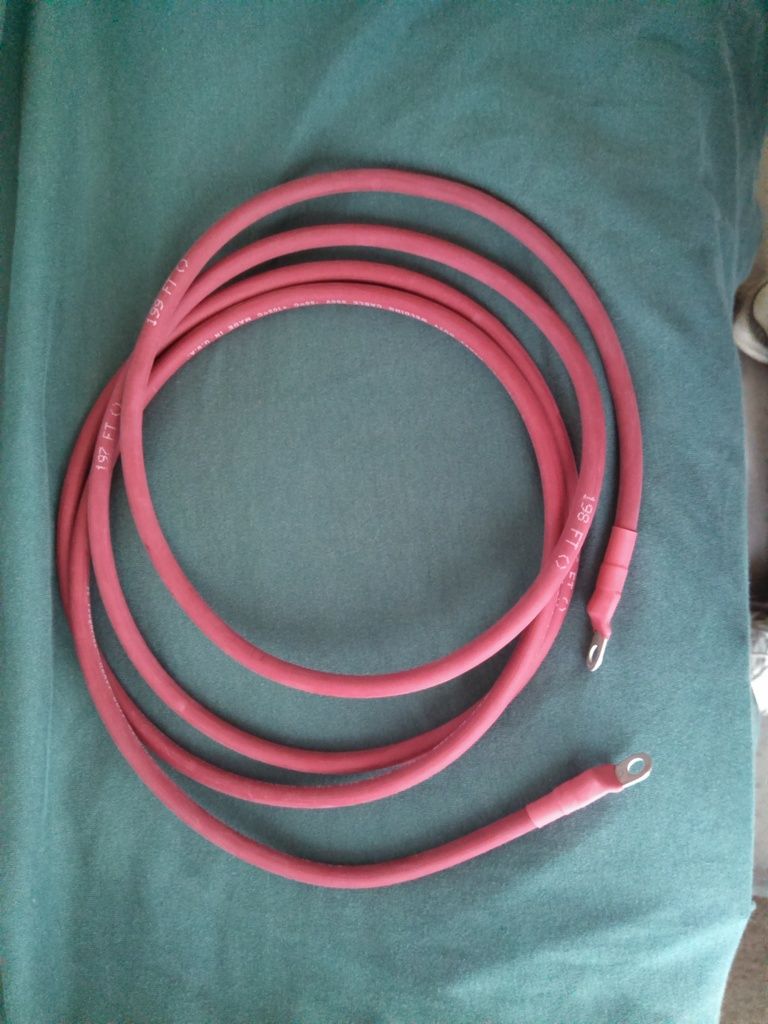
Here's a pic of Ed's 6ga wire around. Wire is a US made product. It has a protective boot for the alternator end isn't in the pic... DOH!!!!

Here's a pic of Ed's 6ga wire around. Wire is a US made product. It has a protective boot for the alternator end isn't in the pic... DOH!!!!
lol ...was just about to ask about the boot ...then I read it .... its been a pleasure rob ...next job is eliminating the ballast and ecu and getting the all in one msd dizzy figured out.
KitCarlson
Well-Known Member
Your diagram shows the engine to bulkhead ground removed. Was it replace with another? The system needs a ground to the body.
slmiller243
Active Member
- Joined
- Mar 29, 2009
- Messages
- 42
- Reaction score
- 0
We just switched to an MSD Ready to Run distributor. You have already done all the hard work. Several good threads that give all the info you need. Basically remove all the old electronic ignition components and extra wires and hook the wires together at the ballast resistor.
I unwrapped the wiring to the coil, distributor and section going to the ballast/ECU. I kept the blue wire for the positive lead on the coil and got rid of all the old coil and distributor wires. Also eliminated the wire that went from the ECU to the ballast resistor. You can clean the wiring up even more by cutting the wires at the old crimp connection, getting rid of the extra wires and splicing what is needed back together. It is obvious once the wiring is unwrapped.
I unwrapped the wiring to the coil, distributor and section going to the ballast/ECU. I kept the blue wire for the positive lead on the coil and got rid of all the old coil and distributor wires. Also eliminated the wire that went from the ECU to the ballast resistor. You can clean the wiring up even more by cutting the wires at the old crimp connection, getting rid of the extra wires and splicing what is needed back together. It is obvious once the wiring is unwrapped.
killnine
Well-Known Member
Why bypass the meter? It could still be useful in the chain. As long as you're providing a better path between the alternator and the battery I would leave it connected.
Why bypass the meter? It could still be useful in the chain. As long as you're providing a better path between the alternator and the battery I would leave it connected.
It doesn't provide any useful info with a wire running direct from alt to starter relay, unless you build some type of shunt.
JoesEdge
Well-Known Member
SB69GTS - Do you have more info about your alternator? Like...what part number, model, does it need special brackets, etc... That's one of my next upgrades.
The Altenator was a powermaster 7519. They painted it black for me for no extra cost. Its a square back and I am using the VR to keep it kinda stock looking. All my brackets were used and no special mods required if reg. 318/340 heads are used. I had to make some spacers and bring out the pulleys a bit .... went with indy x heads and alternator was tight to the head so I just added spacers. I checked my 340 heads and they are recessed abit on the front of the head to allow for the alternator ...the indy heads are flat up front.
-


