Nope, not ignition switch.
It's why I asked "what doesn't work."
At this point I would suspect the BLACK connection right at the ammeter, that is the wire end itself OR the "welded splice."
At this point problably need to yank the cluster out of there
Be absolutely certain you have power on both studs of the ammeter. If you do it's one or the other of the above.
So far as your service manual, here's an alternative. These diagrams are not always accurate, and don't always show all connectors and plugs. But they "can be" easier to follow.
http://www.mymopar.com/index.php?pid=31
These two
http://www.mymopar.com/downloads/1974/74ValiantA.jpg
http://www.mymopar.com/downloads/1974/74ValiantB.jpg
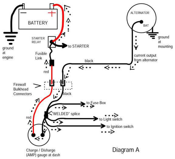
Start with diagram "A" and find "J" in the bulkhead connector. This is the HUGE thick labled RED wire going off the right of the page. This represents the INTERIOR side of the bulkhead.
Now go to diagram "B". This is simply the way they are "printed."
Find that huge RED coming in at the left of the page, follow it up, through the ammter. This is battery power coming TO the ammeter
So at this point you have come from battery---fuse link---bulkhead connector----red wire---to ammeter---through ammeter---out on the BLACK wire---and off to the left of the page
Now go back to diagram "A"
Find the huge BLACK coming in at the right of the page, and follow to "P" of the bulkhead connector. this contiues out in the engine bay to the ALTERNATOR
Now backtrack that black just past coming in at the right of the page. That splice you see there is the "welded splice." This splits off to feed
headlights --no fuse the light switch has a breaker
hot feed to the fuse panel
and feeds off "large black" to the ignition switch going TO the switch
To repeat one last time, this is why the MAD diagram is so cool......it shows in one small diagram all this "crap" LOL