67Dart273
Well-Known Member
Without knowing what all you are doing, this is tough. Is the battery disconnected? I've forgotten "what all" and "where all" you've been
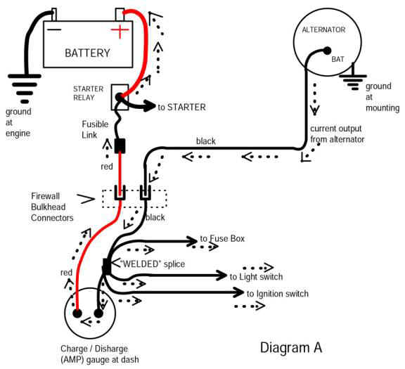
The black wire to the ammeter (speaking her of factory wiring) comes off the ammeter --goes through the bulkhead connector -- and to the output stud of the alternator. DEPENDING ON which way you have your ohmeter (it has a battery) you will trigger the alternator diodes "forward biased" and gain a path through ground..
This ground path MIGHT be what is causing your reading, "coming back" from ground up through one of the loads on the blue wire
The blue is IGN1 often called "ignition 1" This feeds lots of stuff, depending on the year, and IS NOT FUSED
On earlier cars, it feeds power to the dash gauges through the instrument regulator
the dash cluster warning lights ---oil, brake, etc
and branches off, goes out through the bulkhead connector and feeds the ignition system and IGN terminal of the voltage regulator
70/ later, depending on years, this IGN1 also feeds the alternator field (blue) and some smog doo - dads, like, idle solenoid or advance retard if used, etc.
The ignition switch ALSO gets it's main power feed, as does the fuse panel "hot buss" off that same black ammeter wire.
Here, read this:
http://www.madelectrical.com/electricaltech/amp-gauges.shtml
and the diagram down the page:
........gives you a good idea of power distribution in these cars. You can see the "welded splice" in the black ammeter wire. This is a factory welded splice a few inches from the ammeter, up in the dash harness, and branches off and feeds several things as indicated. THIS IS NOT FUSED. The headlight switch has a breaker in the switch.


