1968 Plymouth Valiant First Gen HEMI

-
I would have posted this earlier in the week but I ended up spending most of the time setting up a new computer as my old one is on the verge of dying. I think the only thing I hate worse than setting up a new computer is setting up a new phone.


We’re back to having an empty engine bay. The mock-up engine and transmission have left the building and are back at the machine shop and transmission shop respectively.


https://flic.kr/p/2qzG3Qr]eng compartment[/url] by https://www.flickr.com/photos/153889607@N08/]M Patterson[/url], on Flickr


The next step will be finishing up the transmission tunnel and mocking up the master cylinder relocation bracket and building a couple of brake lines.


The last thing we did before pulling the mock-up motor was to screw some studs into the passenger head to see if the Moon valve covers could be removed over the studs or if I would have to use bolts to attach the cover. Fortunately, it just clears. The problem with using bolts for the valve covers is the bolt holes go into the water jackets. If you use bolts, you end up having to drain the cooling system to pull the valve covers or make a heck of a mess.


I actually like the old PAW covers I had on the engine, the problem was the gasket lip on the bottom of them is extremely wide (I had to change them out on the 57 Plymouth because they interfered with the steering box). They also gave very little clearance to the passenger inner fender of the Valiant.
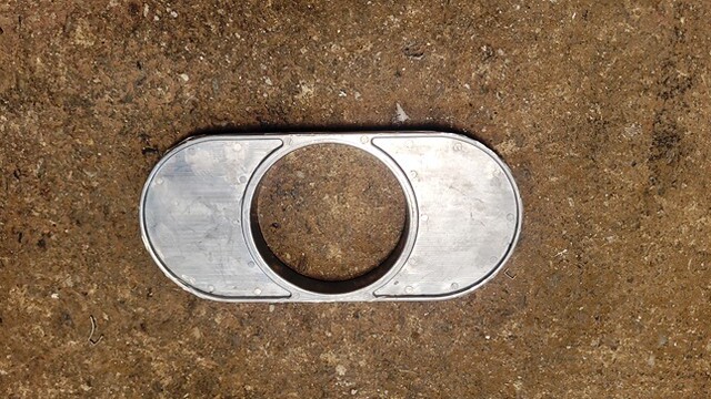
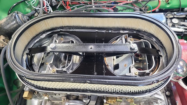


https://flic.kr/p/2pWe3VW]intake carbs[/url] by https://www.flickr.com/photos/153889607@N08/]M Patterson[/url], on Flickr


The Moon covers were installed on the HEMI. I’m still getting used to them after having looked at PAW covers on the engine for the last couple of years. I like them, it’s just getting used to them. Oh well the PAW covers were sold at the swap meet a few weeks ago anyway.


So the engine is back together and running again.

https://flic.kr/p/2qzG2T1]VC1[/url] by https://www.flickr.com/photos/153889607@N08/]M Patterson[/url], on Flickr


https://flic.kr/p/2qzHkwi]VC2[/url] by https://www.flickr.com/photos/153889607@N08/]M Patterson[/url], on Flickr


I want to play with the idle a little more then it will be moved to a cart and the transmission attached. With the weather being colder now that it’s winter I’m not getting a lot of shop time so that may take a while.
 
What a cool build. I’m glad I found it today. Keep up the good work!
 
Your master cylinder relocation bracket, you can find at Mopar performance, They used them on the 68 Hemi Cuda and Darts
 
Thanks for the info on the bracket. The only thing I found on the Mopar Performance site is the one that moves the MC to the left. I’m going to try to use the bracket the moves the MC up (I’ve used both on customers cars in the past).


I realize the brackets that kick the MC up is designed to use with a booster and the ratio for the pedal is wrong for manual brakes, but I think I’ve figured out how to solve that. Now all I’ve got to do is get a couple warm days out in the shop to find out.
 
You could try and fit power brakes on it, Factory a body booster and MC. I did it on my 67 with the Hemi

IMG_1597.jpeg


IMG_5212.jpeg
 
Man I like looking at the pictures of your engine compartments.


“…..You could try and fit power brakes on it …..”


That’s an option I’ve in the back of my head for a while if I can’t get the manual brakes to work out. I did a similar conversion on a customers car several years ago. He managed to find an aftermarket dual diaphragm unit that as I recall was a bit smaller in diameter than yours. I wish I could remember the company he got it from, but he passed several years ago and the cars in his collection got scattered to the 4 winds.
 
you could use a remote mounted servo, it could go anywhere there's room even under the dash in the car. if you master cylinder is dual circuit then either 2 remote servos or one of the double ended dual remote ones.
neil.
 
The one that you are looking at is Original to my 67 Convertible. I used the offset mount from Mopar Performance. And the power booster bracket lifts the booster up and above the valve cover. I picked up a NOS one off Ebay a few years ago for a spare. You are welcome to it if you decide to go that route. I'll have to look but if I remember it had all the brackets that supported the booster to inner fender and firewall as well
 
I sure do appreciate the offer, but I think I have everything I need on hand already. (But you know how that goes LOL)
 

Between the weather and a health scare, it’s been a while since I had much time to work on the Valiant.

Now that were back at it, we decided to get the fuel system sorted out. As I found out when sorting out the first car I built when I moved to Arizona in the mid-80s, vapor-lock can be a real issue on a carbureted daily driver where I live.

Besides the heat being the major cause for vapor-lock additional aggravating factors include altitude (I’m at 4500ft and often travel to higher elevations), and oxygenated (ethanol) fuel (E10 is the most common and available premium fuel in this area). Basically where I live I hit the trifecta for vapor lock.

After going thru a lot of the typical “fixes” for vapor-lock on that first Arizona build, I found the only real fix on a low pressure fuel system was to run a return line. This keeps the fuel moving thru the system and prevents the heat buildup that will cause the fuel to boil in the fuel line. With that in mind I started collecting the parts for the fuel system.

When I bought the new gas tank, I also orders a new sending unit to go along with it. There are currently be 2 sending units readily available for these cars. One for a 5/16” fuel line and the other for a 3/8 fuel line. I chose the 3/8” one in part because it has a nipple for fuel return line.

https://flic.kr/p/2qSrDcr]Sending unit[/url] by https://www.flickr.com/photos/153889607@N08/]M Patterson[/url], on Flickr


Next up was collecting the rest of the parts for the rest of the fuel system and building what I needed to meter the fuel being returned to the tank. Before anybody comments about my fuel pump choice, I’ll be covering that in my next post.


https://flic.kr/p/2qT4BRC]Fuel system[/url] by https://www.flickr.com/photos/153889607@N08/]M Patterson[/url], on Flickr

When I finally installed the fuel return system on that car 35 years ago, I was using a fuel pressure regulator to control the amount of fuel bypassed back to the tank. Back then I had a heck of a time getting one that would work properly or last very long. I finally solved that problem by replacing the regulator with a fitting containing a fixed orifice.

https://flic.kr/p/2qSxBj9]Bypass[/url] by https://www.flickr.com/photos/153889607@N08/]M Patterson[/url], on Flickr

Somewhere along the line I figured out that a 1/4” NPT fitting/pipe is the correct ID to run an 1/8” NPT tap through. Then I use an 1/8 recessed pipe plug with a hole drilled in the center as the metering device. The hole size doesn’t appear to be very critical, I’ve used as large as an 1/8” hole and as small as 1/16” …..for this one I’m starting out with a 5/64th” hole .

Some may also note that the fitting on the return line I’m using a compression fitting rather than a flair fitting. Believe me normally I do not use compression fitting on anything automotive. In this case it was what I could find that would work……from a safety stand point it should do fine. Under normal conditions pressure in the return line will probably be under 1 PSI, in the worst case, (like the return line becoming blocked) the fuel pump I’m using has a max pressure of 6 PSI.

Personally I liked the cleaner look of the fuel line I originally built for the engine on the test stand.


https://flic.kr/p/2qT6dxP]Fuel Line 1[/url] by https://www.flickr.com/photos/153889607@N08/]M Patterson[/url], on Flickr


The return system I built is definitely a case of function over form. I want the return to start as close to the carburetor as possible or in the case of multiple carbs at the furthest carb in the system.


https://flic.kr/p/2qTiebh]Return line[/url] by https://www.flickr.com/photos/153889607@N08/]M Patterson[/url], on Flickr


Basically it is what it is. Given the choice of how it looks and nursing a vapor-locking car home, I can live with it .


When the fuel tank was installed a while back, we went ahead and started getting the fuel lines installed. When I got the car, the fuel lines were the flexible braided type and run down on the drivers’ side. For this build it actually works better to have the lines coming down the passenger side, so a new 3/8” steel fuel line was run. Rather than re-invent the wheel the 5/16 fuel line was removed from the parts car, cleaned up, checked and installed on the Valiant to use as a return line.

https://flic.kr/p/2qSvH3i]return line[/url] by https://www.flickr.com/photos/153889607@N08/]M Patterson[/url], on Flickr


We decided to run the lines up the back of the engine so we terminated the them just forward of the firewall.

https://flic.kr/p/2qSrcy2]fuel lines[/url] by https://www.flickr.com/photos/153889607@N08/]M Patterson[/url], on Flickr


The HEMI has no provision for a mechanical fuel pump, so I picked up a couple of universal electric pumps. I know that some will question my choice on these particular pumps. I was quite leery myself when I bought my first one over 35 years ago (at that point I had tried a few different pumps that hadn’t worked out for various reasons and was at the point where I was willing to try anything).

https://flic.kr/p/2qGknGH]fuel pump[/url] by https://www.flickr.com/photos/153889607@N08/]M Patterson[/url], on Flickr


Surprisingly they actually work quite well. I’ve run them as the sole fuel pump on several engines over the years and have not run into any fuel starvation issues, (keep in mind the engines have been street motors under 375 C.I.)

The pumps are available in 4-6 PSI and 4.5-7 PSI. I normally use the 4-6 PSI version and the only modification is to upgrade the included 1/8 NPT X 5/16 barb fitting that come with them to 1/8 NPT X 3/8 barb.

I also have these installed on all of my carbureted cars even the ones where the primary fuel pump is an engine driven mechanical pump. For those vehicles they’re wired to an on/off toggle switch and used to fill the fuel bowl after the car/truck has sat for several days (saves a lot of wear and tear on the starter motor). The design of the pump allows fuel to be sucked through when the pump is in the off position.

These pumps have also proven to be pretty reliable, over the last 35 years or so I have only had a total of 4 go bad (about the same failure rate I’ve had with mechanical pumps driven similar mileage).

When I built the car that I had the vapor lock problems with, I actually ended plumbing 2 pumps in series with each pump being wired to one leg of an on/off/on switch (as mentioned I was pretty leery about the first one I bought and changing one out on the side of the road is not pleasant). As the design of the pumps allows the rear pump to have gas sucked thru it when it’s off and the front pump will allow fuel to be pushed thru it when it’s off, it does not cause an issue with 2 pumps plumbed in series in the fuel line. That system worked system worked well so I left the “extra” pump in the system. After about five years of trouble-free operation one of the pumps did go out. It was really nice to reach under the dash and simply throw the switch to the other pump, finish my trip and then replace the bad pump at my convivence. Because of that experience I started installing 2 pumps on all my vehicles that rely solely on electric fuel pumps. Because of the 3 position switch (on/off/on) it also makes a good anti-theft device. In the off position the car will still start, but will only run as far as the fuel bowls will allow (about a block).

https://flic.kr/p/2qV6BT3]Fuel pumps[/url] by https://www.flickr.com/photos/153889607@N08/]M Patterson[/url], on Flickr


We still have a bit of work to do like connecting the electrical and relocating the return line a little higher but it’s pretty close to finished.

I normally make up the fuel lines so the pumps are in a “low” spot in the fuel system which causes the fuel to stay in the pumps when the engine is shut down (instead of draining away from the pumps). That way the pumps don’t lose their prime and have an easier job pulling fuel from the tank on start-up.

These are a “clicker” type pump and when they are dry they are pretty loud, however when they’re actually pumping fuel the noise is hardly noticeable (Personally I can’t hear them over the exhaust when the engine is running……but I’m old LOL). I normally switch the pumps over every few months just because.

As this has worked very well for me in the past I have no reason to believe it will be any different in the Valiant.
 
We managed to get a couple of other small things taken care of.

One was blacking out the front of the core support. When the sun hit the front of the car just right that green paint on the core support really stood out and just didn’t look right to me.……much better now.

https://flic.kr/p/2qUT4pg]CS BO[/url] by https://www.flickr.com/photos/153889607@N08/]M Patterson[/url], on Flickr

The other little project was converting to cable operated hood latch operated from inside the car (yes, there are assholes out there who think it’s perfectly OK to open the hood of a strangers car ……I’ve run into a couple of them). I’m not sure if the cable operated latches were optional on the 68 Valiants, but my latch is good and it was just easier to convert it and add a new cable from Amazon than it would be to dig up on original latch and cable….. if available…..and most of the used factory cables I’ve seen have cracked handles anyway.

Unbolting and removing the factory opener handle was straight forward. The mods to the latch itself were also pretty simple. A split bolt to hold the cable end was installed and then a small bracket to retain the end of the cable housing was fabricated and welded to the latch assembly.

https://flic.kr/p/2qWaRnP]Latch Cable[/url] by https://www.flickr.com/photos/153889607@N08/]M Patterson[/url], on Flickr


And mount the handle to the dash.

https://flic.kr/p/2qWeYGa]hood release[/url] by https://www.flickr.com/photos/153889607@N08/]M Patterson[/url], on Flickr
 
We got what should be about the last of the work we needed to do to do to the body before the engine and transmission goes in, reinforcing the crossmember brace in the trans tunnel.

The brace that we needed is 2” across, so I started with a ¼” X 2” piece of flat stock, To get the shape roughed out I clamped the piece we cut out in the vice and then clamped the piece of flat stock to that. With a lot of heat and hammering we finally had a piece we could work with.

https://flic.kr/p/2qMtYNq]tunnel brace[/url] by https://www.flickr.com/photos/153889607@N08/]M Patterson[/url], on Flickr

After several trips under the car for final tweaking it was welded in and then my grandson got to spend some quality time with the grinder cleaning up the welds and shooting some paint on it.

https://flic.kr/p/2qYLuNZ]tunnel brace (2)[/url] by https://www.flickr.com/photos/153889607@N08/]M Patterson[/url], on Flickr

It's a little hard to get a good picture of it, in person it actually looks pretty good. Between that piece ¼” flat stock stock and the welded in subframe connectors I don’t think there will be any issues.

The rest of the day was spent getting the engine off the run stand and removing the bellhousing, flywheel and spacer plate.

I got it mounted on the engine cart this morning and next will be getting the adapter and transmission mounted. After that will be sorting out throttle and kickdown brackets and the kickdown cable. Then I guess we’ll see it all fits LOL.

https://flic.kr/p/2qYWRQJ]Eng 46RH[/url] by https://www.flickr.com/photos/153889607@N08/]M Patterson[/url], on Flickr


.
 
The engine and transmission will be going in as a unit so next up was bolting the transmission on. I’m using Hot Heads early hemi to small block 727/904/518/500 transmission adapter. I’ve used these before and they’re a pretty good kit. The included flexplate is drilled for 3 different convertor bolt patterns and so far I haven’t found one it doesn’t work with.

The instructions that come with the adapter are pretty minimal, so some figuring out is required.

https://flic.kr/p/2qZmECv]Trans adapter inst[/url] by https://www.flickr.com/photos/153889607@N08/]M Patterson[/url], on Flickr

Doing the installation can be a bit of a pain, but it’s one of those jobs you should only have to do once. The kit includes hardware, but the bellhousing bolts are Allen head cap screws and I replace all but 1 of those with a regular hex bolts.

https://flic.kr/p/2r1gidc]354 46RH[/url] by https://www.flickr.com/photos/153889607@N08/]M Patterson[/url], on Flickr

Rather than cover the specifics involved in installing the adapter, if you’re interested in the details, I did a write-up for another forum that covered installing the same adapter on another project. On a side note this adapter should also work on the Pre-1962 poly engines with the long crankshaft overhang to if you want to upgrade to a more modern transmission. The installation of the adapter is located at:

http://www.clubhotrod.com/mopar-426-hemi/15090-general-hemi-info-part-3-a.html

(fair warning, that site has a lot of outages so if you can’t get in try every few days).

Now with the transmission installed I can get started on the other fun stuff like kick-down linkage and cooler lines, lock-up and OD switches etc.
 
I spent some time sorting out the new throttle, kickdown and cruise control brackets and cables while the engine and transmission was still out.

Throt KD Cruise by M Patterson, on Flickr


Kickdown by M Patterson, on Flickr


With that taken care of the engine and transmission were finally installed. Right off it was evident that the high mount alternator and compressor brackets were a non-starter. I was kind of expecting this problem so it was no surprise.

ZZ Upper brackets by M Patterson, on Flickr

I had built all the brackets that were on the HEMI, so other than some time I really don’t have any money tied up in them. At some point I’ll put them up for sale along with the PS pump brackets and make a few bucks on them. Fortunately, Hot Heads sells low mount brackets that should alleviate the problem. Theare also designed for use with a Sanden 508 compressor and GM style 10 SI alternator which is what I was running and will locates the components on the sides I want.

ZZ Low brackets by M Patterson, on Flickr

It also looks like we have an issue with oil filter/torsion bar interference, but all that will take is a different oil filter adapter.

Still a long to do list, but it a good feeling seeing the engine and transmission in its new home.

Eng inst by M Patterson, on Flickr
 
We’ve been getting the to do list whittled down a bit.

The oil filter adapter came in and was installed. I’ve used this style before and I’m not necessarily a fan but it does cure the filter interference problem. The upside down position of the filter makes for messy oil changes, but my biggest complaint is when the car sits for several day the oil will eventually drain back so when it’s started the filter must refill before the rest of the oil system is pressurized.

https://flic.kr/p/2r5UrMs]zz filter adapter[/url] by https://www.flickr.com/photos/153889607@N08/]M Patterson[/url], on Flickr

https://flic.kr/p/2r5Ub51]zz filter adapter 2[/url] by https://www.flickr.com/photos/153889607@N08/]M Patterson[/url], on Flickr

I also got the low mount AC and alternator brackets and belts sorted out and installed. I would have liked to have run both belts over the water pump pulley but that put the AC belt too close to the lower radiator hose so I used a shorter belt that just runs from the crank pulley to the compressor.

https://flic.kr/p/2ramBdr]Low Brackets[/url] by https://www.flickr.com/photos/153889607@N08/]M Patterson[/url], on Flickr

The hood from the parts car was mated to the car for the first time. After some adjustments it actually fits pretty well and without air cleaners the hood actually shuts. With the air cleaner it will definitely will need a scoop for clearance.

https://flic.kr/p/2rbyhyq]Hood[/url] by https://www.flickr.com/photos/153889607@N08/]M Patterson[/url], on Flickr

The 2 projects we’re currently working on are the “hood scoop” and exhaust.

We’ve got the initial hole cut in the hood and I’m currently working on the air cleaner base.

https://flic.kr/p/2rdBowX]Air Cleaner hole 1[/url] by https://www.flickr.com/photos/153889607@N08/]M Patterson[/url], on Flickr

A lot of the “hood scoops” I looked at were just a little short for the air cleaner I plan on using. I finally settled on a steel Goodmark cowl induction scoop (2 ½” tall). As delivered it is way too long so I currently taking measurements to trim the length a bit. Current plans are to cut the hole in the hood to match the cut down scoop, flange the edge to the lip fits as flush as possible then spot weld it too the hood.

For a short time I had hopes I could use a Six Pack air cleaner on it but it was just a bit wide for the scoop and I’ll be using Ford style Dual Quad/Tri-Power air cleaner as I had originally planned.

https://flic.kr/p/2rdWRdu]Cowl scoop[/url] by https://www.flickr.com/photos/153889607@N08/]M Patterson[/url], on Flickr

The exhaust system is proving a bit problematic. Before anybody asks why I don’t just take it to a muffler shop, I would IF there was one locally that consistently did good work. I’ve been building my own for the last 10-15 years, right after I had the 3rd one come back that had to be redone due to interference issues.

The crossbar the front of the ladder bars connect to make it a bit tight to get the mufflers in but we’re making progress on that, just a bit more cutting and bending.
 
The /6 used a tube in the oil filter area to keep the oil level above the tube, which is higher than without the tube. Maybe a /6 oil filter tube thingie will help the filter hold oil better. (Sorry, no pics handy.)
 
Thanks Mike, I’m aware of the oil pipe on the /6s, hadn’t thought about using one but something to think about.

Thanks for bringing up the anti-drain back valves Neil. I had been under the impression that all WIX filters had them, but when I looked it up before posting I found out that’s not correct. I appears that they are only in the XP and racing lines (learned something today LOl ).

It looks like the WIX 51515 is the correct full sized filter with the anti drain-back. I’ll probably see if I can find one a bit shorter that interchanges (It will make getting a filter wrench on it a bit easier).

Thanks guys.
 
i don't know if it had a non return valve but the ford efl90 is the same fitment but shorter. not sure if anyone makes an equivalent with the non return valve if not. worth a search to see though.
neil.
 
The Wix 51084 is the shorter version (factory small block size) of the 51515 and it has an anti-drain back valve in it. 51085XP is shorter yet and also has the anti-drain valve.
 
We think alike.....

67-76 A body trans mount built for 8HP70 / 90 install....similar to your mod. Many have used this mount as their starting point for various transmission applications
20240604_103201.jpg
20240604_115612.jpg
20240604_103649.jpg
 
I decided to go down the air cleaner rabbit hole a bit, back to “if you can’t buy, it make or modify it”.

My normal go to filter/air cleaner for dual quads and tri-power over the years has been some version of the early 60s Ford Dual Quad/Tri-Power air cleaner/filter assembly. Replacement filters are readily available from several sources ($35-$40 ea) and several versions of the lids are also available.

https://flic.kr/p/2pWgbq4]DQ AC[/url] by https://www.flickr.com/photos/153889607@N08/]M Patterson[/url], on Flickr

I had planned on using one of these on the HEMI, but by the time I moved it forward enough to clear the firewall and hole in the hood, 6 inches of it were forward of the front carb and it only extended 1 ½” behind the rear carb. It just looked very awkward. I decided to look at other options. I briefly considered a Mopar six pack assembly until I measured (it’s just a bit too wide for the scoop). I needed something that was long enough to cover both carbs, provide sufficient filtered air for the engine at WOT and (a major consideration) have readily available/affordable replacement air filters.

I ended up settling on a 15 X 8 X 2 polished finned aluminum unit that matches the finned aluminum valve covers nicely. Visually it works better than the Ford style filters, and filter elements are currently available at about $20 each (Yeah I ordered a few to stock).

https://flic.kr/p/2rh3GKd]15 X 2 Air cleaner[/url] by https://www.flickr.com/photos/153889607@N08/]M Patterson[/url], on Flickr

There are several versions of this air cleaner available, but all of them had the same base that’s aluminum and for a single 4 BBL carb. I knew this going in and my solution was to cut the center of the base out. From there I attached 2 single 4 BBL bases to the bottom and built hold-down brackets.

https://flic.kr/p/2rgGxc4]Air filter 2[/url] by https://www.flickr.com/photos/153889607@N08/]M Patterson[/url], on Flickr


https://flic.kr/p/2rhKDHT]Air Filter hold downs 1[/url] by https://www.flickr.com/photos/153889607@N08/]M Patterson[/url], on Flickr

Visually it works better than the Ford style air cleaners, although it could stand to be a bit bigger (the big valve covers on the HEMI make a lot of air cleaners look small). The filter itself is a ½” taller than the element on the Ford elements I normally use so air volume should be sufficent. Filter elements are currently available at about $20 each (Yeah I ordered a few to stock). An added plus is with the shorter size I can move the hood scoop back a little further and shorten it a bit more. I’ve got the hood back off and am also currently working on the scoop.

https://flic.kr/p/2rgB3Lp]Air Filter 1[/url] by https://www.flickr.com/photos/153889607@N08/]M Patterson[/url], on Flickr


.
 
The exhaust is finally done. As with most things on this build it took far longer than expected, in large part due to my back. I wanted a full length 2 ½” system. Between the front ladder bar crossmember, track locator bar, coil overs and slightly relocated gas tank it proved a bit challenging.

https://flic.kr/p/2rpvFj7]Exhaust[/url] by https://www.flickr.com/photos/153889607@N08/]M Patterson[/url], on Flickr

For mufflers I’m using glasspacks. The size makes placement a bit easier and I personally I like the sound. My normal method of installation is to weld ball and socket joints on the ends which allows easy R&R of the head pipes/tail pipes if necessary……. I always found it aggravating to have to cut apart a fully welded system to say pull a transmission and then have to weld it back together when the repair was done.

https://flic.kr/p/2rdBnh3]Muffler[/url] by https://www.flickr.com/photos/153889607@N08/]M Patterson[/url], on Flickr

So at the end of yesterday I finally had a pair of tail pipes coming out under the bumper.

https://flic.kr/p/2rpxu9B]Tail pipes[/url] by https://www.flickr.com/photos/153889607@N08/]M Patterson[/url], on Flickr

Now it’s back to working on the hood scoop.


.
 
-
Back
Top Bottom