70 Dart Stopped Charging

-

MattP

Well-Known Member
Joined
Sep 8, 2012
Messages
259
Reaction score
13
Location
Baton Rouge
Car was operating fine, but now does not charge battery.

3 wires coming off alternator. 2 Have voltage when car is running. 3rd has voltage when lights are on. "Using crackedbacks wiring mod if that makes a difference"

2. Voltage regulator on firewall test ok.

3. Small silver block with multiple spade connectors next to battery doesn't have voltage where a couple wires are hooked up . I don't know what this is or what it does.

I know this is vague and I will update with better information if you have questions. I can take a few pics when I get home if needed.
 
Tell us what color of the 2 smaller wires to the alternator has voltage when running. I assume it has one each of green and dark blue (or black) small wires; please confirm. Are you testing for voltage on the 2 smaller wires with them connected to the alternator normally?

What do mean by 2? Did you take the VR somewhere to be test to show it is OK?

Do you have a voltmeter?
 
Grey and black are part of crackedback's wire mod and have voltage when headlights are on. . 2 wires to the right have voltage while car is running.
http://i197.photobucket.com/albums/aa294/Driver500/20140619_071031_zpsmucx2zbe.jpg
http://i197.photobucket.com/albums/aa294/Driver500/20140619_071045_zpsse3nohgk.jpg

http://i197.photobucket.com/albums/aa294/Driver500/20140619_071052_zpsthcsqbrx.jpg
I tested the wire going and and out of the regulator while the car was running and found voltage on both sides. It's loose now but seems like it was grounded to the firewall. I cleaned up the mating surface. There is a wire coming out of the firewall that end about 4" after exiting. No idea what that is/was supposed to go to.
http://i197.photobucket.com/albums/aa294/Driver500/20140619_071110_zpsluehikbk.jpg

This is the block next to the battery I was talking about. I don't know what it is, but when I tested it with a multimeter it didn't have voltage while the car was running at all the terminals.
http://i197.photobucket.com/albums/aa294/Driver500/20140619_071122_zpswu2fi8kn.jpg
 
That silver block is the starter relay. It is not an issue for this problem.

The voltage coming out of the 2 wires in the VR connector....was that very near to 12 volts? If so, then that is normal with the VR unplugged. one or the leads feeds the 12v to run the VR, and the other is the connection to the one side of the alternator's field winding. If I understand your readings, they show that the alternator's field is basically OK.

Also check the terminals up inside the VR connector see if they are clean and not spread out; these can have poor contact at times.

The next test should be to measure the voltage of both of the small terminals on the back of the alternator when things are running and everything connected; just be careful with yourself and the voltmeter leads with the belts and pulley! Have the VM - (black) lead connected to a good ground. (These 2 wires look to be blue and blue/white....is that right?) One should have close to 12v and the other should be lower. Report back the actual voltages that you measure (as in 12.1v or 6.3v).
 
Thanks for the reply and info.

I checked the voltage of the wires going in and out at the regulator with the car running an everything plugged in. One side was slightly lower than the other but both were in the 11.5 - 12v range. From what I could find online this indicated the regulator was working as it should and was not the problem.

I'll double check the voltage of the 2 small terminals on the back of the alternator. Both were in the 11.5 - 12v range if I remember correctly. Wires are blue and blue/pink but this car has been gone through prior to my ownership. I don't think one side was lower. The larger connector that the headlight kit is connected to had zero voltage until the headlights switch was turned on.
 
Checked the 2 smaller terminals. Both read the same 10.4v

Car immediately dies when I remove negative battery terminal.
 
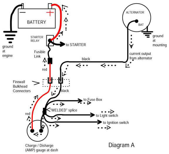
Here is the basic, simplified 70 / later VR and isolated field alternator diagram

Dual_Field_Alternator_Wiring.jpg


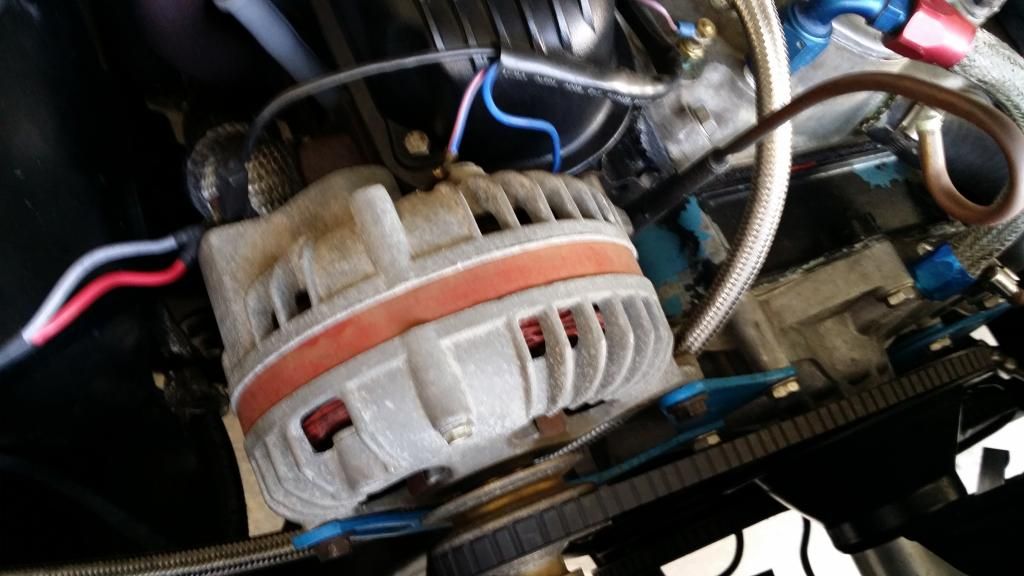
Here is basically what you should have

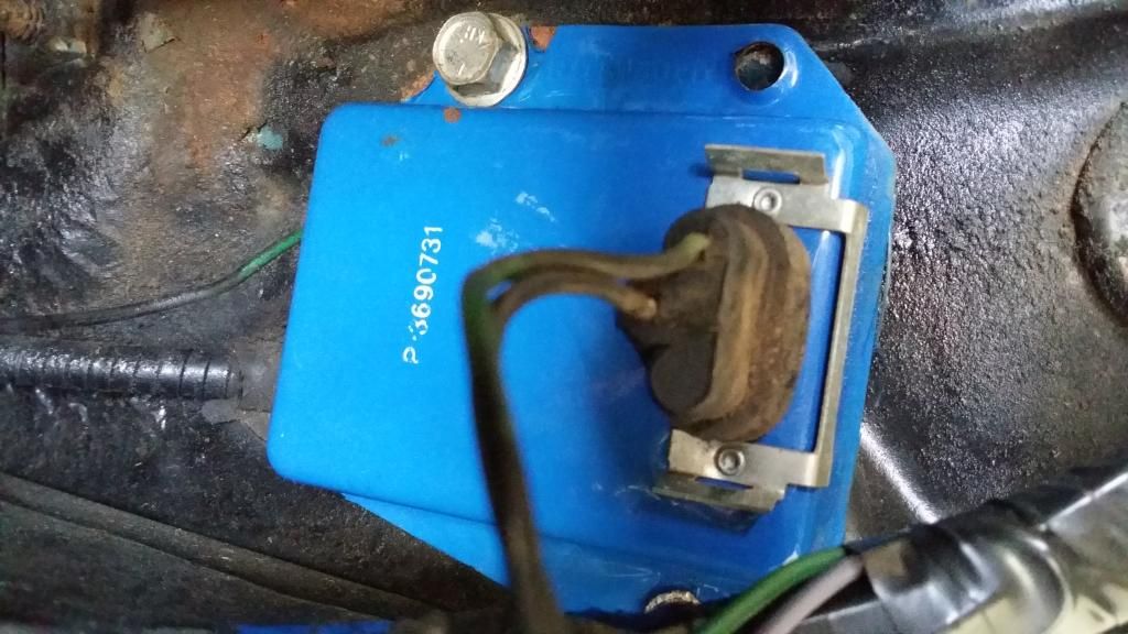
From the ignition switch, top of diagram, power comes down to ballast, junctions and branches off and feeds battery power to one field terminal (matters not which) and to the "I" (IGN) terminal of the VR

The VR MUST be grounded.

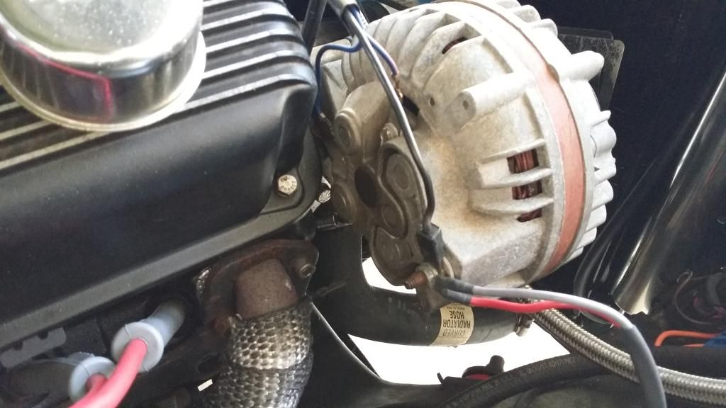
The green "F" wire comes out of the VR and goes to the remaining alternator field. This wire controls the 'amount of ground' so to speak on the field.

So ignition (switched 12V) feeds the field, and the green F wire controls the ground side.

There are several possibilities:

The VR may have lost ground

The VR connector may be internally broken or corroded.

The brushes / field may not be continuous

The alternator may have a different problem.

The battery charging wire from the output of the alternator to the battery may be loose / intermittent/ broken. If you have factory wiring, this is suspect

===================================================

To get started. Remove the green field wire from the alternator field Disconnect the VR plug. If colors are wrong, then pick one, turn the key to run, and see if the remaining field wire still hooked up has 12V. If not, pull that wire off and put the other back on, and recheck

At this point you should have the key in "run," you should have one field wire dangling, and you should have 12V at the one left connected.

Now take a clip lead and connect to the bare field you just unhooked. Touch it to ground, if possible, in subdued light. You should see a small spark. Hook it up

RE measure power at the opposite field wire. You should still have 12V.

Start the engine, slowly bring up RPM and see if it charges. If it does, great

=============================================

Now, re--connect the other field wire, so both are "normal" at the alternator. Move to the VR connector. With the key in "run" both terminals at the VR connector should have 12V. "Make" a jumper (nails, small screws) that will contact the VR plug terminals, and jumper them together.

Go back to the alternator. Disconnect the field wire which you had hooked up in the first test. If colors are correct, this is blue Ground that alternator terminal.

Now check for power, key on, at the green wire field terminal. You should again have 12V. Repeat the charge test. If it charges, these two tests show the field circuit wiring is OK

=============================================================

If in the first test, you got no output, this might be

A bad alternator

Or a broken output charging wire

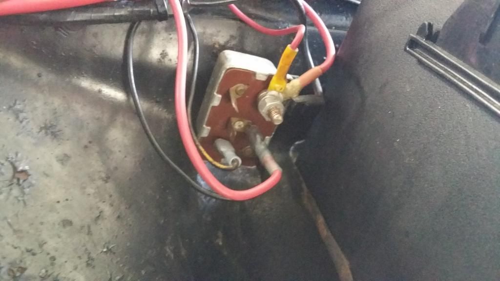
Unhook both field wires. Take one clip lead and ground either field. Take a second clip lead and run over to the "big stud" on the starter relay. Repeat the engine run test

No charge?

With the engine running at a fast idle, check battery voltage. Below 13.XX v means no charge. If it's low, probably 12. something, move your meter over to the alternator stud. If it is about the same as battery, then you have a bad alternator

If this stud voltage is very high, varies with RPM, might be VERY high IE over 17V you have a broken output wire problem

Post back here. I may be gone a day or two. Got some things came up here
 
Is there supposed to be a grounding wire at the VR or does it just ground to the firewall? Mine was made with a plastic coating but I don't see where a wire would connect. Other than a small corner of the plastic that has peeled off and the bolt holes I'm not seeing how it would be grounded.
 
Checked the 2 smaller terminals. Both read the same 10.4v

Car immediately dies when I remove negative battery terminal.
The car dieing would make sense if the alternator was not working. BTW, don't ever remove either battery terminal connection with the engine running and alternator working; the alternator voltage will spike up and often kill the alternator.

Did you check the 2 wires on the back of the alternator with the engine running? If so, then there should be some difference in voltage between the 2 terminals, if the voltages are the same, then the VR is not pulling current through the field like it should.

The VR case normally grounds to the bodywork through the bolts; star washers under the bolt heads will help. You can add a ground lead if you like but the case must be grounded for the VR to work. That could explain the 'no voltage difference' on the 2 smaller alternator terminals.
 
Changed the voltage regulator out for a R296. Now it's still not charging the battery but my voltage readings at the alternator have changed and the ammeter goes from normal to very high at the slightest increase in rpm. Other bulbs such as cluster & headlights also get brighter with rpm when they haven't before.
The large terminal is at 14.5v. The blue/pink wire is zero and the blue wire is 12.5v.

Before I swapped the regulator I had no voltage at the large terminal unless the lights were on "using cracked back wire mod" and the two other poles were identical.
 
The ammeter laying over MAY be because the battery is down quite a bit

Measure the battery voltage right at the battery terminals, watch voltage and the ammeter and raise RPM while doing so.

If the voltage stays below 15V but the ammeter lays over, then the battery is simply low, and it's charging

You description therefore is contradictory. You say the "large terminal" (where on the alternator?) is 14.5--------(when---at all times, with engine revved, ??)

Do the lights seem OVERLY bright? Again, if the battery is low, the lights would be DIMMER than normal with engine off or idling slow, and might be simply "coming up to normal" with system voltage at 14.xx


Battery dropped from 14.5v to 12.5v idling for a few minutes after these reading were taken. I was hesitant to drive it around if it was overcharging.
 
If the above is correct, IT IS NOT charging.

It appears to me that you have a break in your output wire between there and the battery. Now when I say "break" this might mean "a real bad connection."

Review this article. Even if you don't perform this mod, it has a review of how this all works, and the causes

http://www.madelectrical.com/electricaltech/amp-gauges.shtml

Pay particular attention to the diagram on the above page:

amp-ga18.jpg


In the above diagram, this is a simplified representation of the main power distribution in these old girls. "Follow along."

From the battery, to the starter relay stud, through the fuse link (which might but problably is not a problem............

through the bulkhead connector on the RED wire, your first "suspect."

Next we go to and through and out the ammeter, your next three suspects

The next suspect is back out the bulkhead connector on the BLACK wire going back to the alternator

It's possible but rare that the wire end right at the alternator is bad

Rare but HAS HAPPENED is the welded splice has failed on the black ammeter wire. This si a factory welded splice up under the dash, which branches off to feed

the headlight switch (headlights only power)

the hot buss in the fuse panel

the feed to the ignition switch

couple of other things on some cars
 
-
Back
Top