Alternator not charging

-
OK, next step would be to check output stud at alternator with same conditions, IE compare battery reading with the alternator output stud.

The best way to test these systems is to NOT use any Auto/whatever tester. Test the system on the car.

Read carefully what I asked you to do, and if not understanding, post back with questions.

The major "blocks" of failure are...............

1...Field circuit and regulator

When you check for battery voltage / key on at the blue field wire, and with the green wire grounded, you are checking all the way from the battery, through the bulkhead, ignition, and all the way to the field, through the alternator field and to ground.

2...problems in the output wiring

The output of the alternator comes out of the big stud, through the big black wire, through the bulkead, ammeter, back through the bulkhead, fuse link, and to the battery. By comparing these readings with the system charging AFTER you have checked the field circuit, you can usually tell if this circuit path has problems, such as bad connections in the firewall/ bulkhead connector

3...problems in the alternator

If you cannot get it to charge by bypassing the regulator in (1) and the test in (2) seems OK, then it's likely bad problems in the alternator. This can be as simple as sticky or worn brushes, a bad (open or grounded) field winding, or bad stator and or rectifier diodes.

I'll say it again.........the chances that two alternators have exactly the same problem on someone's tester is fairly unlikely.

This stuff is generally not magic. It is a "logical" as Mr Spock
 
73 has a white connector in engine harness. The alt wires run through that connector. If its bad the alt field isn't properly powered. The alt doesn't function right. Just a guess.
 
What brand model is your multimeter? Does it have a current scale? (amps / milliamps?)
 
What brand model is your multimeter? Does it have a current scale? (amps / milliamps?)

It is a matco digital, I'm not sure will have to check (amp/milli) etc when I get home. But I've tested the alt stud during idle (batt reads 12.2 stud reads 11.1) test blue field(batt 12.2 blue field 9.8) tested grn field(batt 12.2 grn field 0.7) all these readings with everything hooked up and idling.
 
OK that indicates not charging. "Charging" assuming battery is not completely dead and no dead cells, should run no lower than 13.5 up to nominal 13.8....14.2 and no higher than about 14.5----14.7

So what next?

Backtrack

If you have a charger then charge up the battery. If possible have it load tested. Do not allow the guy running the tester to mistake a discharged (dead) battery for a bad battery

Then backtrack on your testing.

Unhook both field wires from the alternator

Hook a clip lead from one alternator field terminal to ground

Hook a clip lead from the remaining alternator field terminal over to the big stud (battery) on the starter relay

Slowly bring up RPM and see if it charges. If not recheck your alternator stud voltage, you want the engine idling FAST as "cold idle."

What I suggested back in post #6. This is the basic "does it work" test, divorcing the alternator from the car's wiring as much as possible and see if it works then. This hookup is similar to how they would test it on a machine in a parts store.

I would add, if the dash ammeter doesn't show charging, measure the voltage difference from BATT- to the output stud of the alternator and to the body of the alternator. The body should be 0V, especially if you connected the case jumper I suggested. The output stud should read >13V, even >15 V if the path to the battery is open. You can add your own direct path to BATT+ using 12 awg wire (minimum), and many people make that permanent. Melted terminals in the bulkhead or ammeter are common, due to the high current + corrosion. Once you get it working, add back the car's wiring one at a time until you finger the culprit.

Ok I did as dart273 stated and unhooked both field wîres. I then hooked a clip lead to ground and the other I tried to hook to battery stud on starter relay but couldn't because it would spark way to bad when i tried to clip. What does that mean??
 
It should spark "some." Once again, if you can give me details on your multimeter, we can help you hook it up to measure current. The field should draw several amps (there is some controversy over the years in the shopmanuals, but somewhere around 3--4.5 amps I believe)

Another thing you want to do is with both the field wires unhooked, set your meter up for resistance (ohms) and measure from each field terminal to ground. You should read infinity (open) on either terminal.

An example of a popular problem:

One field brush holder can break or maybe someone left the insulator out, grounding it. What this means is you have created a 50-50 gamble. If you hook battery to the field terminal which is grounded, you have a short. If you hook it to the opposite terminal, the alternator will charge "full blast."

Also, the field can develop an internal short which causes it to draw way too much current. I could see that this might burn up the regulator.
 
ok im having same issue but i just changed the points style to hei setup so i got rid of the ballast resistor is there some kind of diagram for that
 
It should spark "some." Once again, if you can give me details on your multimeter, we can help you hook it up to measure current. The field should draw several amps (there is some controversy over the years in the shopmanuals, but somewhere around 3--4.5 amps I believe)

Another thing you want to do is with both the field wires unhooked, set your meter up for resistance (ohms) and measure from each field terminal to ground. You should read infinity (open) on either terminal.

An example of a popular problem:

One field brush holder can break or maybe someone left the insulator out, grounding it. What this means is you have created a 50-50 gamble. If you hook battery to the field terminal which is grounded, you have a short. If you hook it to the opposite terminal, the alternator will charge "full blast."

Also, the field can develop an internal short which causes it to draw way too much current. I could see that this might burn up the regulator.

Ok since you said it would spark a little, I tried once more, and once I got it all the way on the battery stud on starter relay it went up in smoke and burnt the crap out of my hand. Soooo that's not good, lol. Also car has zero power now, could I have damaged something further by this happening? Also my multimeter is a matco MD582.
 
Sounds to me like that alternator has a problem. Are you CERTAIN you did not have the clip lead touching ground at the field terminal?

When you reduce "the circuit" to a test setup like this (which is intentional) you have got "things" down to a very simple form.

The brushes, both supposed to be insulated (isolated) from ground, contact the field, which is nothing more than an electromagnet. You should be able to run 12V into one brush with the other grounded. This should result (with the engine running) in full alternator output

So either you got your clip lead against ground, or that alternator has a shorted field/ broken brush, etc.
 
OK found a good photo of your meter on ebay, lol.

First you want to check the field for shorts. With the probes into their "normal" spots, the two far right hand jacks, and the switch set for ohms (200 at top left) measure from each field terminal to ground. CHECK the meter by shorting the probes which should read near zero. When checing the field terminals to ground, want the OPPOSITE of this, that is, infinity, or open.

If that checks out, measure field current...............


I'm guessing? that when you put the switch in the high current position (in order to measure amperage) that it mechanically uncovers the two jack positions on the left? To measure current in this case, you would set the switch toward bottom left to 20 in the blue (which is DC) and not 20 in the white (which is AC)


You would want one probe plugged into the far right jack (common) and the other into the far left jack (max 20A fused). Always hook an ammeter in series, not across, as you would a voltmeter.

In other words you would have a clip lead at ground-----other end to one field. Second field to one ammeter probe, other ammeter probe to the starter relay.

Notice that the jack says "max 20A fused." These use a special internal fuse, that are fairly expensive, several dollars each. So at least the meter is fairly protected
 

Attachments

  • md582a.JPG
    125.7 KB · Views: 241
" Always hook an ammeter in series, not across, as you would a voltmeter.

In other words you would have a clip lead at ground-----other end to one field. Second field to one ammeter probe, other ammeter probe to the starter relay." K. Ok I don't quiet understand what you mean right here. I do understand the rest of it, unfortunately we got bad weather now so I can't work on it right now
 
Think of the alternator field as a simple light bulb. You have the alternator, forget the alternator, just think about the field. The field is a definate, separate object, connected by the brush terminals, just like a light bulb. If you want to see why the "light bulb" is burning up wiring or blowing fuses, you need to determine if it's shorted, or for some reason, drawing too much current

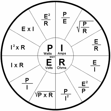
So one test you might make is resistance. You can calculate approximate resistance with ohm's law, which is I = E /R

In english means AMPS = VOLTAGE divided by RESISTANCE

You can look up Ohm's law pie charts to make that easier

Like this

ohmspie-450x450.gif


In this case we know voltage, we can measure and determine amperage and we want to know in advance if this is reasonable so we don't burn something up, like you did with your clip lead

So looking at the pie chart, upper right, I (amperage) the formula you want is still voltage divided by resistance or E/R

So measure the resistance of the two brushes with your meter set at 200 ohms. Let's say it measures about 4 ohms. Plug that into your formula, divide voltage (12.6v nominal for the battery) by your 4 ohms, and you get.................3 amps. This means you can expect to measure about 3 amps with your meter hooked up in series for current

So with the meter set for 20A DC as I said above, you can "rig" the circuit path

clip to ground.....................clip to one field.

Second field connected to one probe............................other probe to battery positive

So what you have there is a series circuit.

ground..................field terminal..............through the field..............out the second field terminal............to the meter probe............through the meter..............out the second meter probe...........to battery positive.

With the switch set for amperage, you should be able to confirm that the field is drawing that much current, about 3--4--4.5 amps

Again, checking it first with the meter is only determining if there is a short to ground.

To conclude this ramble, I think either you accidently touched the second ground clip at the field terminal to the case, or else the field is grounded, which is what you do NOT want.
 
Maybe this helps some. Start out by checking your meter. In this first photo, the probes are not hooked to anything, and the meter is set on ohms. The display (yours may be different) indicates an open or infinity.

(On mine, this does not mean 0 or zero ohms. It's "OL" or overload, which on a Fluke means infinity)

In the bottom photo, the two probes are shorted together. Here, the meter says .3 ohms, very close to a dead short
 

Attachments

  • _MG_7722cs.jpg
    89.8 KB · Views: 230
  • _MG_7723cs.jpg
    85.7 KB · Views: 224
Next, check the alternator field resistance. Here, we put one probe first on one brush (field) terminal, then the same probe we shift to the second field terminal.


The second probe remains on ground (case) of the alternator. You should show an open, or infinity
 

Attachments

  • _MG_7724cs.jpg
    141.8 KB · Views: 234
Next, we want to check THROUGH the field. This time, we hook one probe to one field, and the second probe to the remaining field terminal. Here, the meter shows about 4 ohms. Rotate the pulley some to sort of "average out" the reading
 

Attachments

  • _MG_7725cs.jpg
    154.4 KB · Views: 244
Last we can check current flow. This mockup imitates your battery, the power supply is set at nominal 12.6 volts, or about the same as a charged battery.

The red wire at far left on the power supply represents the battery stud on the starter relay. A little hard to see, but this is connected to the black meter probe

The meter is set up for amperage now, and even though my meter is different than yours, you still must move the red probe to the A jack, far left on your meter.

So the red probe hooks to the yellow clip lead, and to one of the alternator field terminals.

The remaining field terminal is hooked to the black power supply lead, in other words goes to ground in your car for this test

You should rotate the pulley to measure, this one is showing about 5 amps, "reasonable" under these conditions.
 

Attachments

  • _MG_7726cs.jpg
    104.4 KB · Views: 221
  • _MG_7727cs.jpg
    92.8 KB · Views: 226
Ok dart I haven't done your test yet but will when I pick up a couple more clip leads. But an update I did the easy ammeter bypass and ran a 8 gauge wire from alternator stud straight to the battery stud of starter relay with a breaker right before starter relay stud(also left the stock ammeter wiring on)same thing no charge slowing draining still. So yea new alternator new voltage regulator and wire from alternator straight to batter + and nothing.
 
Hey 67dart the above test you posted with the photos what exactly am I testing by doing that? Am I testing if the alternator is good? Btw tried 2 different new voltage regulators and still nothing. Also I did a complete ammeter bypass still nothing.
 
Sounds like you didn't try my simple "does it work" test. Apply the field current yourself w/ jumpers. Not sure why you put a breaker in the output path to the battery. You always want an alternator connected to the battery, otherwise bad things can happen, especially with newer car electronics.

The other thing that people suggested is to use jumper cables from the alternator's frame to BATT-. You need that return path. As mentioned, that was the problem for me once.

As a final rant, old Mopar alternator w/ Vreg is VERY SIMPLE. I just finished trouble-shooting a "no charge" from the alternator in my 1985 M-B, which uses the Motorola internal Vreg system common in GM Delco cars. What confusion. The "D+" output isn't just a monitor, it requires applying a small current thru the warning bulb to get the thing to "boot up" and start self-generating a field current. My problem was from changing to LED's in the dash cluster. Also, burnt out bulbs = "no charge" there.
 
Not to beat a dead horse, but just be aware that the counter help at the generic auto parts stores are NOT trained technicians.
Doesn't make 'em bad people, but it certainly can result in bad test results. Also remember that they are there to sell you stuff.
Surely, no salesman would ever tell a customer that they had a bad part in order to make a sale - that would be WRONG!

BC
 
Ok with clip leads I grounded one field and the other I hooked to battery positive like y'all said, and still nothing. So with that said that means my alternator isn't working, right?
 
Ok took brand new ALT to advanced it tested as good. So what does that mean when I use clip leads to the battery and still no charge? I mean it's down to a simple form, but does charge. I'm fed up bout to sale this thing.:banghead:
 
It is not clear to me what you are doing. READ this thread again

Ground one field terminal with a clip lead

Hook the remaining field terminal to a battery source

Run the engine, it does NOT charge, is that correct?

Ok, NOW READ UP

Hook your multimeter to the alternator OUTPUT stud, run the engine and see what you have for voltage. Speed up the engine to a fast idle while doing so.

If the voltage is low, 12.5 volts or less it is NOT charging

If the voltage is really high, say, 16 or so, and the ammeter shows nothing, move the multimeter to battery and re-check. If the battery voltage is low, say, 12.5 or less, then you have a ..............

BREAK IN THE charging circuit from the alternator to the battery

This means a BAD connection in the bulkhead connector, or a BAD connection in the ammeter circuit

READ this thread AGAIN
 
-
Back
Top