You are using an out of date browser. It may not display this or other websites correctly.
You should upgrade or use an alternative browser.
You should upgrade or use an alternative browser.
Ammeter to Voltmeter...who does it?
- Thread starter billytuffnuts
- Start date
-
Rbob
Well-Known Member
Redfish, Had to do it, changed the needle:

Much better.
Much better.
Redfish, Had to do it, changed the needle:
Much better.
Agreed. 2 thumbs up
Rbob
Well-Known Member
With 13.8 Volts

I adjusted mine to show 12 volts at 12 o'clock. The trimmer pot' on the gauge has a tiny dab of adhesive to hold it at the factory setting.. Easily defeated .
I will get my + and - connections where my IVR is connected.
I still haven't decided what to do with the original amp gauge wires.
I will get my + and - connections where my IVR is connected.
I still haven't decided what to do with the original amp gauge wires.
One point here is to justify the reading "as installed." If there's enough harness drop that the reading is somewhat different from "actual battery" then it's not very helpful.
What are you doing in this regard?
What are you doing in this regard?
Rbob
Well-Known Member
I don't know if I will have an issue, installing all new wiring with one power distribution point. Since the gauge is used only for reference, if it is past the halfway mark and charging life will be good and if it drops below halfway I will assume there is a problem and investigate.
Logan
Well-Known Member
The actual needle movements are the same for an ammeter and a voltmeter. Each responds to a tiny amount of current applied to its coil. Too much current and the movement is toast.
If it is applied as a voltmeter, there is a relatively large (value- not size)resistor added inside the case- in series- that resists current flow to the movement thereby allowing a tiny current to flow through the coil. Size the resistor right so that the guage reads "12v" when connected to a fully charged 12v battery and your volt meter is good to go.
If you want an ammeter, you will connect a very low resistance in parallel with the coil movement so most of the current will go through the resistor and only a tiny amount through the meter movement. Again, it is calibrated by using the right size resistor to read amps.
If I were to convert to a voltmeter, I'd grab a few voltmeters from fords or chevies next time I was at the junk yard, break them open, isolate the resistors and measure their values with a digital ohmeter. Then, break into the Mopar ammeter, remove the parallel shunt resistor and add the junk yard resistor- or radio shack equivalent- in series and maybe even outside the meter case if it was easier. Change the 'A' to a 'V' and go cruzin.
The actual needle movements are the same for an ammeter and a voltmeter. Each responds to a tiny amount of current applied to its coil. Too much current and the movement is toast.
If it is applied as a voltmeter, there is a relatively large (value- not size)resistor added inside the case- in series- that resists current flow to the movement thereby allowing a tiny current to flow through the coil. Size the resistor right so that the guage reads "12v" when connected to a fully charged 12v battery and your volt meter is good to go.
If you want an ammeter, you will connect a very low resistance in parallel with the coil movement so most of the current will go through the resistor and only a tiny amount through the meter movement. Again, it is calibrated by using the right size resistor to read amps.
If I were to convert to a voltmeter, I'd grab a few voltmeters from fords or chevies next time I was at the junk yard, break them open, isolate the resistors and measure their values with a digital ohmeter. Then, break into the Mopar ammeter, remove the parallel shunt resistor and add the junk yard resistor- or radio shack equivalent- in series and maybe even outside the meter case if it was easier. Change the 'A' to a 'V' and go cruzin.
Maybe where the amp meter has a coil. These amp meters measure in a magnetic field. Well sort of . The actual magnet is on the armature. The brass shunt has not resistance. Just a cool conductor. Volt meter does have about a mile of winding on a coil.
If I were to convert to a voltmeter, I'd grab a few voltmeters from fords or chevies next time I was at the junk yard, break them open, isolate the resistors and measure their values with a digital ohmeter. Then, break into the Mopar ammeter, remove the parallel shunt resistor and add the junk yard resistor- or radio shack equivalent- in series and maybe even outside the meter case if it was easier. Change the 'A' to a 'V' and go cruzin.
Sorry, disagree. A series resistor --known as a multiplier--depends on the individual movement, I.E. a movement for a Ford MAY (or may not be) vastly different for a Chivvy.
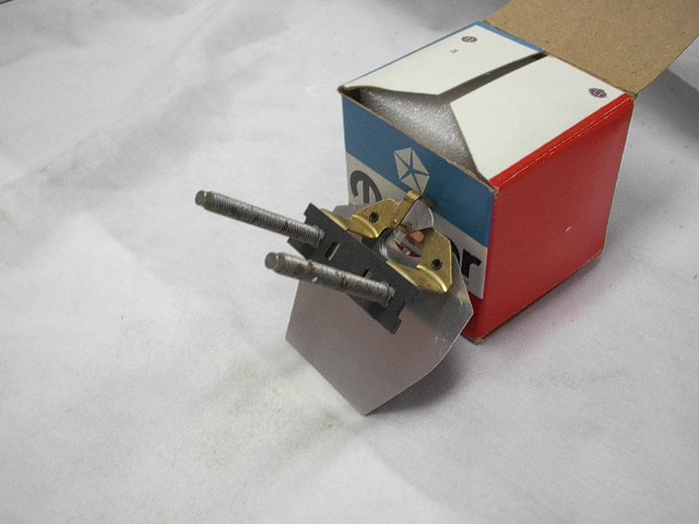
Not only that but you can NOT remove the shunt from a Mopar ammeter of the type the car in this discussion originally used--because it is simply a huge piece of brass that causes needle deflection directly. That is, the "old school" Mopar "full current" ammeter HAVE NO meter movement "as such."
Only ammeters used in some of the later model cars (Mopars) that were external shunt are candidates for conversion such as you describe, and an experimental approach is probably more effective than messing with dissecting GM/ Ford units.
Here's a picture of a Mopar unit--just a brass shunt and a "moving vane" attached to the needle:
Logan
Well-Known Member
I just wrote a long reply only to have it crap out when my picture had a bad extension so excuse me if this is too brief...
Amp and volt meter needle movements are the same. Just a little coil that forms an electromagnet and moves a needle.
Connected as a voltmeter, there's a high ohm resistor in series that minimizes elec flow through the sensitive movement.
Connected as an ampmeter, there's a low ohm resister in parallel that shunts most of the electrical flow away from the needle movement.
Get a junk Chev or Ford voltmeter, cut it open, see if you can remove the series resistor or at least measure its value before going to Radio Shack. Remove the shunt resistor from the Mopar amp meter and install the correct series resistor and the sex change is complete.
This sketch shows the difference. You wouldn't connect it quite like this in the car because you wouldn't want the volt meter energized with the key off. I would suggest connecting the two heavy ga wires that went to the old Mopar amp guage together, connect a light ga wire to this same joint, connect the wire to the hot side of the newly configured guage and a second wire from the other side of the guage to ground. It is now a volt meter.
Attachments
Logan
Well-Known Member
I don't know what happened... I replied a second time and now both are there. Crap!
I know typical after market guages work as I have described. It looks like I should have dragged out my instrument cluster before commenting.
Since we know they are being converted, I guess we'll just have to figure out how. Either by changing the circuit or slipping in a new movement.
I suppose I always wanted a voltmeter anyway. I'll be back.
Sorry, Logan you are simply incorrect as regards the Mopar ammeter. Take a good look at the picture I posted. The entire "meter" consists of nothing more than a brass shunt across the terminals, with a moving vane attached to the needle. There is no coil.
In order to get it to measure "volts" would require it to draw it's full scale amperage.
In other words, if you WERE to convert it to read voltage, the end result would draw what the ammeter drew at full scale, say, 60 or 70 AMPS
I don't know about you, but that's not a very good way to build a voltmeter.
Regardless how they work,slipping in the Sunpro volt gauge is the simplest answer for anyone who is worried about their amp gauge.
We should consider ourselves lucky to have found a substitute that fits the enclosure with minimal effort.
We should consider ourselves lucky to have found a substitute that fits the enclosure with minimal effort.
Here is a suggestion my brother threw out there late last night .
Go ahead and place both original amp gauge terminals on the volt gauge positive stud. Route the ground path of the volt gauge through a N/O relay. Back to the workbench. LOL
Go ahead and place both original amp gauge terminals on the volt gauge positive stud. Route the ground path of the volt gauge through a N/O relay. Back to the workbench. LOL
russduanegreen
Well-Known Member
Just saving for future
Anybody have a pic of the mods to the back side of cluster? I would just like to see the mods there, please?
There aren't any required mods to the back of the instrument housing itself.
Attachments
cudajim
cudajim
I still like the ammeter because it not only tells you that you're charging, it also tells you how much you're charging (or discharging).
I still like the ammeter because it not only tells you that you're charging, it also tells you how much you're charging (or discharging).
Mine doesn't, just hash marks. I have no idea how many amps it is reporting \ i /
Burntorange70
Well-Known Member
Good info! I have wanted to do some thing like this to my Darts rally dash.
Scroll back to my earlier post. There are no mods required to the housing. The gauge drops right in the factory holes.Does anyone have a pic of the mods to the backside of the cluster? I am needing to put some sort of gauge in.....
I put that red paper label from the Sunpro gauge on there rather than throw it away but it's not concealing anything.
Fellas,
I am installing a voltmeter in a tripod under the dash (along with oil and water) in my 65. Where is a good Hot spot to hook the positive side keyed lead to? Was thinking ignition side of the fuse to then to ground.
Anyone have any luck?
I am installing a voltmeter in a tripod under the dash (along with oil and water) in my 65. Where is a good Hot spot to hook the positive side keyed lead to? Was thinking ignition side of the fuse to then to ground.
Anyone have any luck?
-
Similar threads
- Replies
- 16
- Views
- 844
- Replies
- 3
- Views
- 386
- Replies
- 10
- Views
- 768


